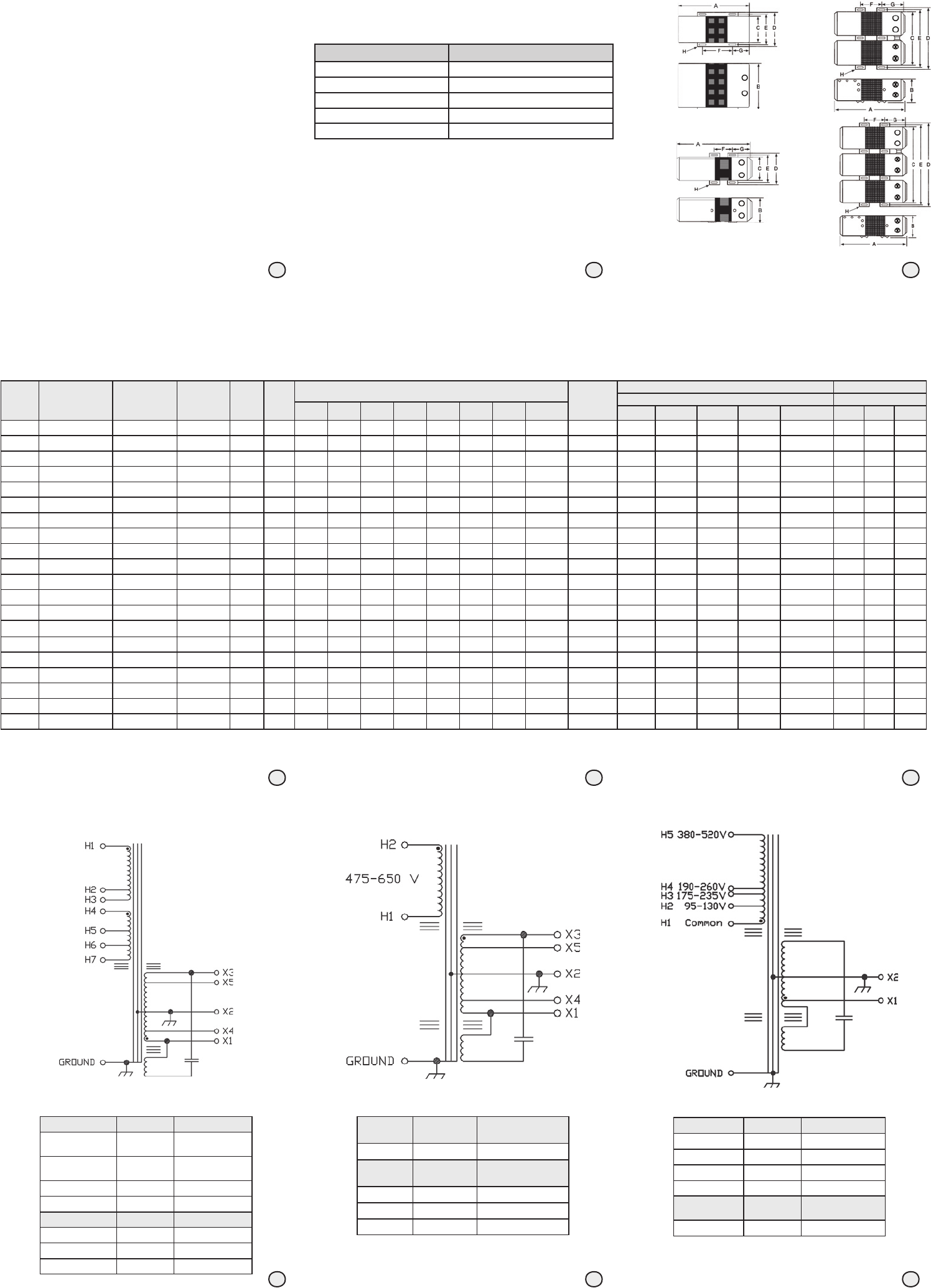
Figure 6. 500–3000 VA Electrical Connection
Primary
Voltage
Interconnect Connect Lines To
600 H1 & H2
Secondary
Voltage
Interconnect Connect Lines To
120 X1 & X2 or X3 & X2
208 X4 & X5
240 X1 & X3
Figure 5. 5000–15000 VA Electrical Connection
Primary Voltage Interconnect Connect Lines To
208
H1 to H4
H2 to H5
H1 & H5
240
H1 to H4
H3 to H6
H1 & H6
480 H3 to H4 H1 & H6
600 H3 to H4 H1 & H7
Secondary Voltage
Interconnect Connect Lines To
120 X1 & X2 or X3 & X2
208 X4 & X5
240 X1 & X3
Figure 7. 60 Hz 120–250 VA Electrical Connection
Primary Voltage Interconnect Connect Lines To
120 H1 & H2
208 H1 & H3
240 H1 & H4
480 H1 & H5
Secondary
Voltage
Interconnect Connect Lines To
120 X1 & X2
Operating & Service Instructions
Sola Minicomputer Regulators
UL White Card Listed – Power Supply Classification
CSA Certified – Transformer Classification
General Description and Specifications
The Sola Micro/Minicomputer Regulator (MCR) provide virtually instantaneous voltage
regulation, and isolation from both transverse and common mode noises for any type of
load. It also suppresses transients with ferroresonant, protects overloads, and serves as a
dedicated line. It is the ultimate in AC power conditioning equipment.
Operating Temperature Range: -20° to +50°C.
Phase: Single
Input Voltage and Frequency: See Table 2
Output Voltage and Frequency:
120, 208, or 240, 60 Hz
Output Voltage Regulation:
+3% for an input line variation of +15%
Output Harmonic Distortion: Less than 3% total RMS content at full load.
Efficiency: 90% at full load typical. No loss of output for line loss of 3 msec.
Noise Reduction: Common mode noise rejection exceeds 120dB.
Transverse noise rejection exceeds 60dB.
Voltage Surge Suppression: Suppresses ANSI/IEEE C62.41-1980
Class A and B waveforms
(formerly IEEE 587-1980).
60 Hz Mini/Micro Computer Regulator (MCR)
Installation and Operation Manual
Installation
All regulators generate considerable heat and depend on the natural draft air circulation for
adequate cooling. It is important that ventilation openings not be obstructed. Mounting in a
confined or poorly ventilated space should be avoided unless special provisions have been
made for ventilation.
Hard-Wired Regulators
Hard-wired regulators vary in size according to the output power and may be mounted
in either a horizontal or vertical position. If mounted in a vertical position (on a wall, for
example), steel mounting hardware must be selected in accordance with Table 1 for a
secure installation. The wiring compartment should be at the top. Regardless of position,
the regulator should be located where contact with the hot surface of the transformer
is unlikely.
For proper ventilation, allow a minimum of 12 inches of clearance above the unit and a
minimum of 6 inches of clearance on each side. Dimensions of the regulators and the
morning brackets are presented in Figures 1, 2, 3, and 4. The specifications for the figures
are listed in Table 2.
Table 3 defines the regulator connections in relation to the points diagrammed in Figure 10.
Fusing and wire gauge size are detailed in Table 4A and 4B.
Note: Branch circuit protection must be located in the primary of each transformer! Not in
the three-phase operation, fuses must be connected in the primary of each unit, not in the
three-phase lines.
On 7.5 and 10 kVA models, the terminal block is located in the right unit. Use only the front
or right side knockouts of the right unit for conduit connections. On 15 kVA models, the
terminal block is located in the middle unit. Use only the front knockouts of the middle unit
for conduit connections.
Two or more models of the same rating may be connected with their input and output in
parallel. However, on models smaller than 5 kVA, do not parallel both 208 V (X4-X5) and
240 VCT (X1-X2-X3). This may damage the output windings.
Rated VA of Regulator Min. Diameter of Steel Mounting Screw
120 #10 Machine Screws
250 1/4” bolts
500 to 1000 5/16” bolts
1500 to 10000 3/8” bolts
15000 1/2” bolts
Table 1
Hard-wired regulators must be connected to a branch circuit in accordance with local and
national electrical codes. Electrical connections are diagrammed in Figures 5, 6, 7, and 8.
Proper wiring is determined by the Figure indicated from the regulator
specifications (Table 2).
If operation from a 3-phase source is required, three hard-wired regulators may be wired in
delta as shown in Figure 10.
Figure 1:
Outline
Drawing 1
Figure 2:
Outline
Drawing 2
Figure 4:
Outline
Drawing 4
Figure 3:
Outline
Drawing 3
VA Voltage Input Voltage Output
Catalog
Number
OD EC
Dimensions
Approx.
Shipping
Weight
(lbs)
Input Voltage Output Voltage
Required Circuit Protection / Minimum Gauge 90
o
C WIRE Min. GA 90
o
C Wire
A
(in)
B
(in)
C
(in)
D
(in)
E
(in)
F
(in)
G
(in)
H
(in)
95-130 175-235 190-260 380-520 475-650 120 208 240
120 120, 208, 240, 480 120 63-23-112-4 1 Fig 7 8.62 5.19 3.31 4.00 3.50 3.00 2.44 .22 x .59 15 3 / 14 3 / 14 3 / 14 1 / 14 - 14 - -
250 120, 208, 240, 480 120 63-23-125-4 1 Fig 7 9.88 7.44 4.50 5.38 4.75 4.12 2.19 .31 x .69 27 6 / 14 3 / 14 3 / 14 1 / 14 - 14 - -
500 120, 208, 240, 480 120, 208, 240 63-23-150-8 1 Fig 8 12.69 6.44 7.78 8.00 8.12 5.62 3.06 .38 x .81 37 10 / 14 6 / 14 6 / 14 3 / 14 - 14 14 14
500 600 120, 208, 240 63-31-150-8 1 Fig 6 12.69 6.44 7.78 8.00 8.12 5.62 3.06 .38 x .81 38 - - - - 2 / 14 14 14 14
750 120, 208, 240, 480 120, 208, 240 63-23-175-8 1 Fig 8 13.69 6.44 7.78 9.00 8.12 5.62 3.06 .38 x .81 52 15 / 14 10 / 14 10 / 14 6 / 14 - 14 14 14
1000* 120, 208, 240, 480 120, 208, 240 63-23-210-8 1 Fig 8 16.75 6.44 7.78 9.00 8.12 5.62 5.25 .38 x .81 62 15 / 10 10 / 14 6 / 1 3 / 14 - 14 14 14
1000 600 120, 208, 240 63-32-210-8 1 Fig 6 16.75 6.44 7.78 9.00 8.12 5.62 5.25 .38 x .81 62 - - - - 3 / 14 14 14 14
1500* 120, 208, 240, 480 120, 208, 240 63-23-215-8 2 Fig 8 16.44 9.03 10.56 12.75 11.75 3.00 5.19 .44 x .69 95 25 / 10 15 / 14 15 / 14 10 / 14 - 12 14 14
2000* 120, 208, 240, 480 120, 208, 240 63-23-220-8 2 Fig 8 17.31 9.03 10.56 12.75 11.75 3.88 5.19 .44 x .69 109 30 / 10 20 / 12 15 / 14 10 / 14 - 10 14 14
2000 600 120, 208, 240 63-32-220-8 2 Fig 6 17.31 9.03 10.56 12.75 11.75 3.88 5.19 .44 x .69 109 - - - - 10 / 14 10 14 14
3000* 120, 208, 240, 480 120, 208, 240 63-23-230-8 2 Fig 8 18.69 9.03 10.56 12.75 11.75 5.25 5.19 .44 x .69 142 45 / 8 25 / 10 25 / 10 15 / 14 - 8 12 12
3000 600 120, 208, 240 63-32-230-8 2 Fig 6 18.69 9.03 10.56 12.75 11.75 5.25 5.19 .44 x .69 142 - - - - 15 / 12 8 12 12
5000* 120, 208, 240, 480 120, 208, 240 63-23-250-8 2 Fig 8 28.19 9.03 10.56 12.75 11.75 8.25 8.88 .44 x .69 222 80 / 4 40 / 8 40 / 8 20 / 12 - 8*** 10 10
5000 208, 240, 480,600 120, 208, 240 63-29-250-8 2 Fig 5 28.19 9.03 10.56 12.75 11.75 8.25 8.88 .44 x .69 222 - 40 / 8 40 / 8 20 / 12 15 / 12 8*** 10 10
7500** 208, 240, 480 120, 208, 240 63-28-275-8 3 Fig 9 26.56 9.03 22.81 25.81 24.81 6.62 8.88 .44 x .69 362 - 60 / 6 60 / 6 30 / 10 - 4 8 8
7500 208, 240, 480,600 120, 208, 240 63-29-275-8 3 Fig 5 26.56 9.03 22.81 25.81 24.81 6.62 8.88 .44 x .69 362 - 60 / 6 60 / 6 30 / 10 25 / 10 4 8 8
10000** 208, 240, 480 120, 208, 240 63-28-310-8 3 Fig 9 28.19 9.03 22.81 25.81 24.81 8.25 8.88 .44 x .69 446 - 80 / 3 80 / 4 40 / 8 - 3 6 8
10000 208, 240, 480,600 120, 208, 240 63-29-310-8 3 Fig 5 28.19 9.03 22.81 25.81 24.81 8.25 8.88 .44 x .69 446 - 80 / 3 80 / 4 40 / 8 30 / 10 3 6 8
15000** 208, 240, 480 120, 208, 240 63-28-315-8 4 Fig 9 28.19 9.38 35.56 38.25 37.22 8.25 8.88 .56 x .69 710 -- 125 / 1 110 / 2 60 / 4 - 0 4 4
15000 208, 240, 480,600 120, 208, 240 63-29-315-8 4 Fig 5 28.19 9.38 35.56 38.25 37.22 8.25 8.88 .56 x .69 710 - 125 / 0 110 / 2 60 / 6 50 / 8 0 4 6
Table 2
*Canadian option: cULus certified units must be ordered by changing “-8” (UL only) to “-C8” **UL Listed Only. Use Group 3 for cULus. *** Leads in the wiring department must be sleeved with 105
o
C sleeving. OD=Outline Drawings EC=Electrical Connections
1 2 3
7 8 9
4 5 6
Courtesy of Steven Engineering, Inc.-230 Ryan Way, South San Francisco, CA 94080-6370-Main Office: (650) 588-9200-Outside Local Area: (800) 258-9200-www.stevenengineering.com
 (25 pages)

 (100 pages)
 Manymanuals.com
 Manymanuals.de
 Manymanuals.fr
 Manymanuals.it
 Manymanuals.pl
 Manymanuals.cz
 Manymanuals.es
 Manymanuals-pt.com
Comments to this Manuals