Delta 36-R31X Instruction Manual
Browse online or download Instruction Manual for Circular saws Delta 36-R31X. Delta 36-R31X Instruction manual User Manual
- Page / 32
- Table of contents
- TROUBLESHOOTING
- BOOKMARKS
- INSTRUCTION MANUAL 1
- TABLE OF CONTENTS 2
- IMPORTANT SAFETY INSTRUCTIONS 2
- CALIFORNIA PROPOSITION 65 3
- GENERAL SAFETY RULES 4
- SAVE THESE INSTRUCTIONS 5
- POWER CONNECTIONS 6
- MOTOR SPECIFICATIONS 6
- GROUNDING INSTRUCTIONS 6
- FUNCTIONAL DESCRIPTION 7
- CARTON CONTENTS 7
- ASSEMBLY 8
- BLADE TILTING HANDWHEEL 9
- EXTENSION WINGS 9
- LVC STARTER BOX TO CABINET 10
- LVC ON / OFF SWITCH 10
- MAGNETIC STARTER 11
- ON / OFF SWITCH 11
- BLADE GUARD AND SPLITTER 11
- FASTENING MOTOR CORD TO SAW 14
- MOTOR COVER 14
- HOLDER BRACKETS 15
- MITER GAGE AND WRENCH STORAGE 15
- DUST CHUTE ADAPTER 15
- RIP FENCE 15
- OPERATION 16
- ADJUSTING 90 AND 45 DEGREE 17
- POSITIVE STOPS 17
- ADJUSTING TABLE 17
- ADJUSTING TABLE INSERT 18
- MITER GAGE OPERATION 18
- AND ADJUSTMENT 18
- REPLACING BELTS AND ADJUSTING 19
- BELT TENSION 19
- CHANGING THE SAW BLADE 19
- MACHINE USE 20
- USING THE UNIFENCE AS A 21
- CUT-OFF GAGE 21
- RIPPING ON LEFT 23
- SIDE OF SAW BLADE 23
- ACCESSORY MOULDING CUTTERHEAD 24
- ACCESSORY DADO HEAD 25
- TROUBLESHOOTING 26
- CONSTRUCTING A FEATHERBOARD 27
- PUSH STICK 28
- MAINTENANCE 29
- ACCESSORIES 30
- WARRANTY 30
- • DELTA SERVICE CENTERS 32
- • DELTA) 32
Summary of Contents
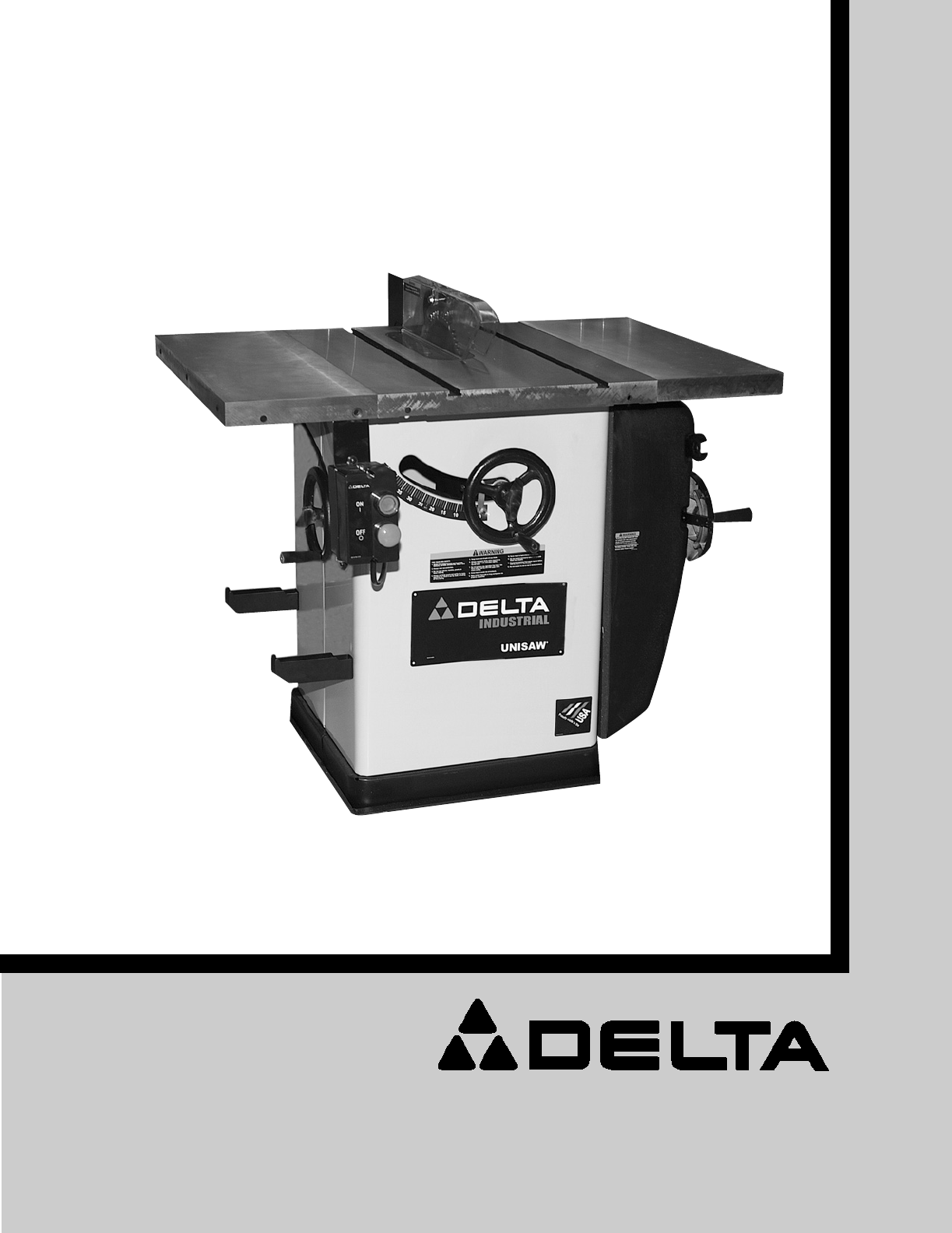
INSTRUCTION MANUALUNISAW®10" Right Tilting Arbor Saw(Models 36-R31, 36-R31X, 36-R51, 36-R51X36-R51L, 36-R53L)PART NO. 422-04-651-0069 - 02-21-05C
10LVC STARTER BOX TO CABINETIf you purchased the machine with magnetic pushbutton electrical controls (LVC), the saw is shipped withthe starter box co
11MAGNETIC STARTER ON / OFF SWITCH1. Locate the magnetic starter switch and hardwarethat was removed in the section “EXTENSION WINGS.”2. Loosely assem
12Fig. 17 Fig. 18Fig. 19Fig. 21Fig. 204. If an adjustment is necessary, loosen two screws (F)Fig. 17, and adjust splitter bracket (A) until it is alig
13Fig. 23 Fig. 24Fig. 25Fig. 27Fig. 269. Insert the front end of splitter (P) Fig. 23, inside thesplitter mounting bracket behind splitter fastener pl
14Fig. 29 Fig. 30Fig. 3213. Holding the clear blade guard, lower the saw bladeand assemble the table insert (E) Fig. 30, into the open-ing on the saw
The Unisaw is supplied with a dust chute connector toprovide a means of connecting a 4" diameter dustcollector hose to the machine. Align the fou
Fig. 39ABFig. 40CFig. 41BLADE RAISING HANDWHEELThe saw blade is raised and lowered with the fronthandwheel (A) Fig. 41. With the exception of hollowgr
17ADJUSTING 90 AND 45 DEGREEPOSITIVE STOPSPositive stops are provided to quickly and accuratelyposition the blade at 90 and 45 degrees to the table. T
18ADJUSTING TABLE INSERTPlace a straight edge (B) across the table at both ends ofthe table insert as shown in Fig. 46. The table insert (A) should al
19REPLACING BELTS AND ADJUSTINGBELT TENSIONDISCONNECT MACHINE FROM POWERSOURCE.1. Remove motor cover to gain access to the motor.2. Place a block of w
2TABLE OF CONTENTSRead and understand all warnings and operating instructions before using any tool or equipment. Whenusing tools or equipment, basic
20COMMON SAWING OPERATIONSCommon sawing operations include ripping and crosscutting plus a few other standard operations of a fundamentalnature. As wi
21Fig. 53ARIPPINGRipping is cutting lengthwise through a board, (Fig. 53).NOTE: Be sure the material to be cut is seasoned, dryand flat. The rip fence
22Fig. 56Fig. 54Fig. 551. Start the motor and advance the work holding it downand against the fence. Never stand in the line of thesaw cut when rippi
23Fig. 58Fig. 57Fig. 59Fig. 60When ripping material with a veneer facing that extendsover the material, the fence (A) should be in thehorizontal posit
24Fig. 61Fig. 64Fig. 62Fig. 63HGWHMoulding is cutting a shape on the edge or face of thework. Cutting mouldings with a moulding cutterhead is afast, s
25Fig. 69Fig. 70Fig. 67 Fig. 68Fig. 661. Dadoing is cutting a rabbet or wide groove into thework. Most dado head sets are made up of two outsidesaws a
26USING AUXILIARY WOOD FACING ON RIP FENCEFig. 71It is necessary when performing special operations suchas when using the moulding cutterhead to add w
27Fig. 72, illustrates dimensions for making a typical featherboard. The material which the featherboard is constructed of,should be a straight piece
28When ripping work less than 4 inches wide, a push stick should be used to complete the feed and couldeasily be made from scrap material by following
29MAINTENANCEPARTS, SERVICE OR WARRANTY ASSISTANCEAll Delta Machines and accessories are manufactured to high quality standards and are serviced by a
3Indicates an imminently hazardous situation which, if not avoided, will result in death or serious injury.Indicates a potentially hazardous situation
30A complete line of accessories is available from your Delta Supplier, Porter-Cable • Delta Factory Service Centers,and Delta Authorized Service Stat
31NOTES
The following are trademarks of PORTER-CABLE •DELTA (Las siguientes son marcas registradas de PORTER-CABLE • DELTA S.A.) (Les marquessuivantes sont de
4GENERAL SAFETY RULES1. FOR YOUR OWN SAFETY, READ THE INSTRUCTIONMANUAL BEFORE OPERATING THE MACHINE.Learning the machine’s application, limitations,
5ADDITIONAL SAFETY RULES FOR TABLE SAWS1. DO NOT OPERATE THIS MACHINE until it isassembled and installed according to theinstructions.2. OBTAIN ADVIC
THIS MACHINE MUST BE GROUNDED WHILE IN USE TO PROTECT THE OPERATOR FROMELECTRIC SHOCK.machine will have a grounding plug that looks like theplug illu
73. Permanently connected machines:If the machine is intended to be permanently connected, allwiring must be done by a qualified electrician and confo
8Fig. 1Fig. 2Fig. 11. Unisaw2. Switch (shown with a magnetic starter)Fig. 23. Extension wing (2)4. Handwheel5. Blade guard and splitter assembly6. Upp
9BLADE TILTING HANDWHEEL1. Install fiber washer (A) Fig. 3, on the blade tiltinghandwheel shaft (B). Install key (C), into shaft keyway.2. Place handw
Related products and manuals for Circular saws Delta 36-R31X


 (100 pages)
(32 pages)
(84 pages)
(2 pages)
(25 pages)
(6 pages)
(12 pages)
(100 pages)
(100 pages)
(32 pages)
(84 pages)
(2 pages)
(25 pages)
(6 pages)
(12 pages)
(100 pages)
© 2020, manymanuals.com. All rights reserved. | 1.720 s |
 Manymanuals.com
 Manymanuals.de
 Manymanuals.fr
 Manymanuals.it
 Manymanuals.pl
 Manymanuals.cz
 Manymanuals.es
 Manymanuals-pt.com
Comments to this Manuals