Delta 78-955 Instruction Manual
Browse online or download Instruction Manual for Circular saws Delta 78-955. Delta 78-955 Instruction manual User Manual
- Page / 12
- Table of contents
- BOOKMARKS
Summary of Contents
INSTRUCTION MANUALBIESEMEYER®10” TABLE SAW BLADE GUARD SYSTEMS(MODEL 78-955 FOR 28”, 30” AND 40” T-SQUARE® FENCES)(MODEL 78-960 FOR 50” AND 52” T-SQUA
Fig. 271024. There is an adjustment screw to achieve the desiredweight of the guard basket (M) Fig. 27, on the workpiece.To make an adjustment, loosen
11Fig.28HMLKNOTICE: BEFORE MAKING ANY ADJUSTMENTS TO THEGUARD BASKET ASSEMBLY, DISCONNECT THE SAWFROM THE POWER SOURCE AND MAKE CERTAIN THESAW BLADE H
Delta will replace, at its expense and at its option, any Delta machine, machine part, or machine accessory whichin normal use has proven to be defect
INTRODUCTIONSAFETY RULES1. FOR YOUR OWN SAFETY, READ INSTRUCTIONMANUAL BEFORE OPERATING THE BLADE GUARDSYSTEM. Learn its application and limitations
UNPACKINGCarefully unpack the blade guard and all loose items from the carton. Figures 1 and 2 illustrate all items suppliedwith the Blade Guard Syste
INSTALLATION4Fig. 3Fig. 4Fig. 5Fig. 6DISCONNECT THE SAW FROM THE POWER SOURCE!IMPORTANT: The following instructions forassembling the splitter illus
55. Locate two bushings each, (K) and (L) Fig. 8, two1/4-20 x 5/8” button head screws (M); two 5/16-18 x 5/8”button head screws (N ) and splitter moun
Fig. 11Fig. 12Fig. 13Fig. 14610. Insert index pin (T) Fig. 11, through the hole in splitter(U), as shown, and fasten with locknut (V). Fig 11 illustra
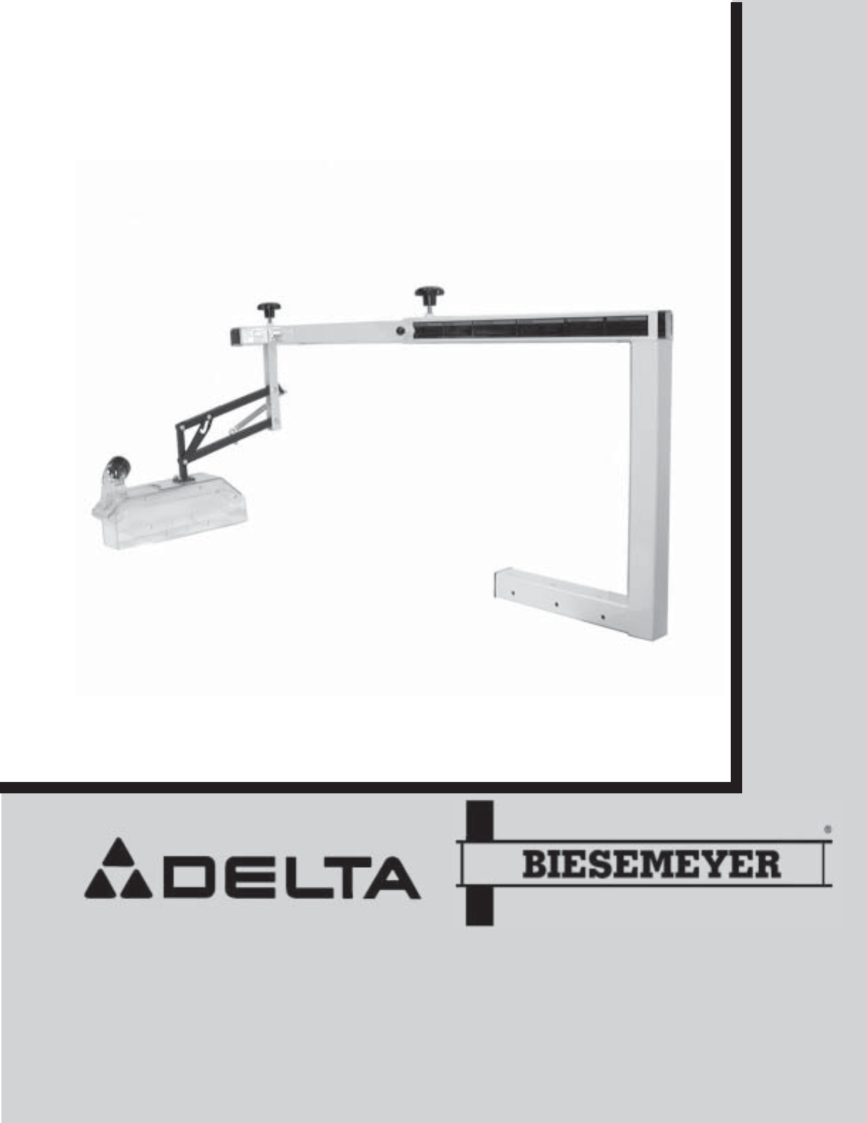
Fig. 15Fig. 16Fig. 17Fig. 18714. Fasten the mounting bracket (A) Fig. 15, to the backrail (B) using the three 2-3/4” long hex head screws (F),three 3-
Fig. 19Fig. 20Fig. 21818. Make certain the hood assembly (M) Fig. 19, is in line withthe basket body assembly (N). When you are certain hoodassembly (
21. IMPORTANT: Make certain the rear end of the guardbasket frame (M) Fig. 22, is 3/8” away from the front ofthe splitter (S) and tighten the two loc
Related products and manuals for Circular saws Delta 78-955
 (24 pages)

 (77 pages) (28 pages)
© 2020, manymanuals.com. All rights reserved. | 1.450 s |
 Manymanuals.com
 Manymanuals.de
 Manymanuals.fr
 Manymanuals.it
 Manymanuals.pl
 Manymanuals.cz
 Manymanuals.es
 Manymanuals-pt.com
Comments to this Manuals