Delta RS830 Instruction Manual
Browse online or download Instruction Manual for Circular saws Delta RS830. Delta RS830 Instruction manual User Manual
- Page / 33
- Table of contents
- BOOKMARKS
- 10" Professional 1
- Radial Arm Saw 1
- TABLE OF CONTENTS 2
- IMPORTANT SAFETY INSTRUCTIONS 2
- CALIFORNIA PROPOSITION 65 3
- GENERAL SAFETY RULES 4
- SAVE THESE INSTRUCTIONS 5
- POWER CONNECTIONS 6
- MOTOR SPECIFICATIONS 6
- GROUNDING INSTRUCTIONS 6
- DISCONNECT MACHINE FROM 7
- POWER SOURCE 7
- FUNCTIONAL DESCRIPTION 8
- CARTON CONTENTS 9
- RADIAL ARM SAW PARTS 10
- TABLE BOARD PARTS 11
- GUIDE TO PARTS 12
- ASSEMBLY 13
- REMOVING BLADE AND 14
- BLADE GUARD FROM SAW 14
- TABLE SUPPORTS 15
- TABLE BOARD CLAMPS AND TABLE 18
- ADJUSTING AND CHECKING SAW 18
- BLADE TRAVEL SQUARE TO FENCE 18
- REMOVING “HEELING” 20
- IN SAW BLADE CUT 20
- CHECKING AND ADJUSTING 20
- SAW BLADE SQUARE TO TABLE 20
- ADJUSTING IN/OUT RIP SCALE 21
- ASSEMBLING BLADE AND 22
- BLADE GUARD 22
- CUTTING INTO TABLE BOARDS 23
- FASTENING SAW TO THE FLOOR 23
- OPERATION 24
- ADJUSTING TENSION ON 25
- ELEVATING COLUMN 25
- CHANGING POSITION OF TRACK 25
- ARM CLAMPING HANDLE 25
- CHANGING POSITION OF 26
- BEVEL CLAMP HANDLE 26
- YOKE CLAMP HANDLE 26
- POSITIVE STOP YOKE INDEX 27
- POSITIVE STOP BEVEL INDEX 27
- ADJUSTING SPLITTER AND 27
- ANTI-KICKBACK FINGERS 27
- MACHINE USE 28
- COMPOUND 29
- MITER CUTTING 29
- OUT-RIPPING 29
- IN-RIPPING 29
- PUSH STICK 30
- MAINTENANCE 31
- TROUBLESHOOTING 31
- ACCESSORIES 31
- WARRANTY 32
- • DELTA SERVICE CENTERS 33
- • DELTA) 33
Summary of Contents
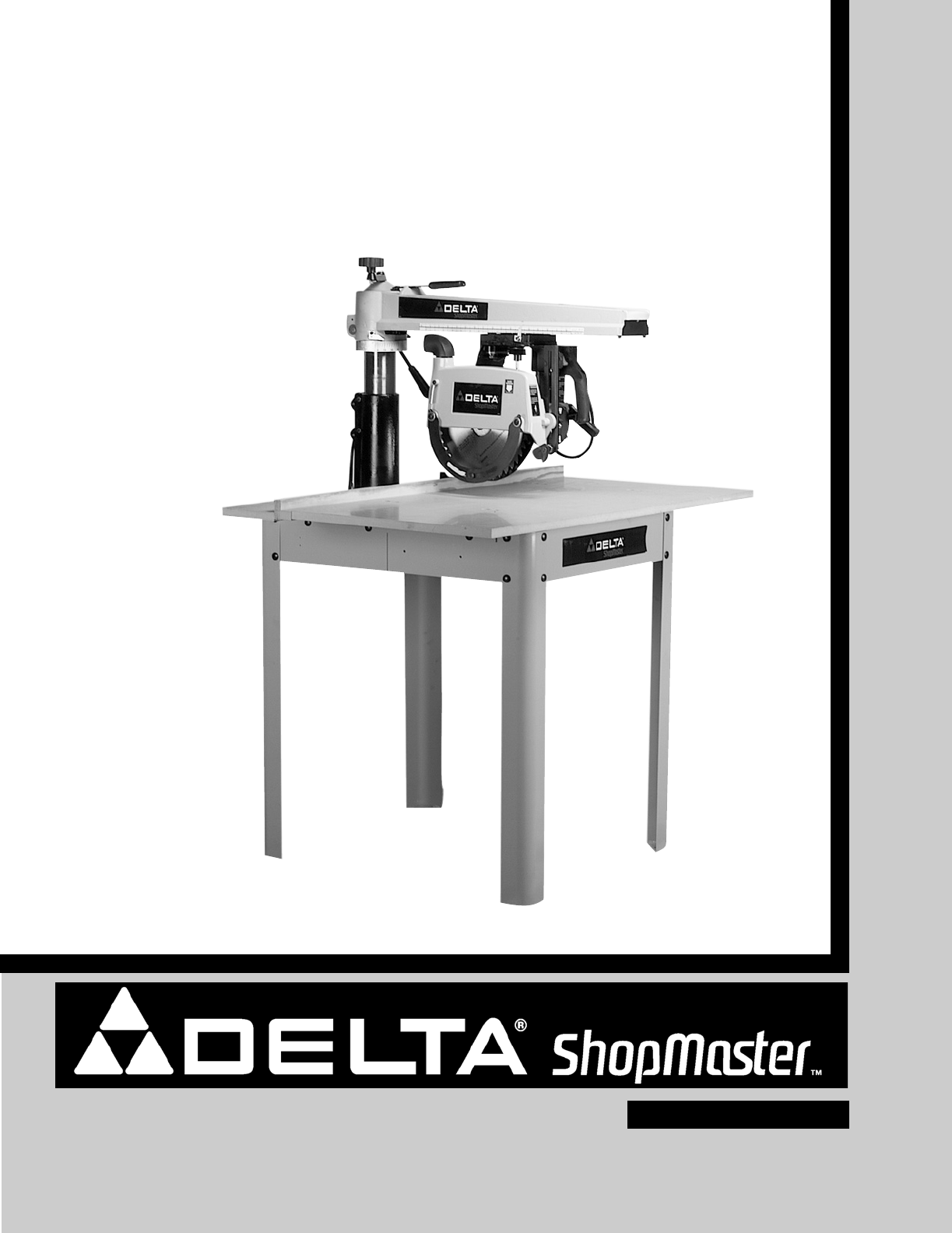
INSTRUCTION MANUAL10" Professional Radial Arm Saw(Model RS830)PART NO. 424-12-651-0034 - 06-17-05Copyright © 2005 Delta MachineryESPAÑOL: PÁGINA
10RADIAL ARM SAW PARTSFig. 41231. Radial Arm Saw2. Legs (4)3. Table Supports (2)4. 5/16-18x5/8" Carriage Head Screws (16)45675. 5/16" Flat W
11TABLE BOARD PARTSFig. 51234561. Fence Board2. Middle Table Board3. Rear Table Board4. Front Table Board5. 7/8" Open End - 1/2" Box Wrench6
12The following is an explanation of the operating controls of the Delta 10" Radial Saw. We suggest you study theseexplanations carefully to fami
13FOR YOUR OWN SAFETY, DO NOT CONNECT THE MACHINE TO THE POWER SOURCE UNTILTHE MACHINE IS COMPLETELY ASSEMBLED AND YOU READ AND UNDERSTAND THE ENTIRE
14REMOVING BLADE ANDBLADE GUARD FROM SAW1. Loosen blade guard clamp knob (A) Fig. 11, androtate blade guard (B) to the position shown.Fig. 11AB2. With
15TABLE SUPPORTS1. Place front table board (A) Fig. 16, on a stablesurface with counter-bored holes facing down, asshown.2. Fasten left and right tabl
166. When both right and left edges of the table boardare the same distance from the table supports, tightenfour screws located in holes (N) Fig. 21,
1711. Place an arbor wrench (D) Fig. 25, between tableboard (A) and motor shaft (B). Lower track arm (X)Fig. 24, by turning elevating handle (C) count
18TABLE BOARD CLAMPS AND TABLEBOARDS1. Locate table board clamps (A) Fig. 29, and insertone clamp into each of the slotted holes (B) located atthe rea
19Fig. 33Fig. 34Fig. 36Fig. 354. Loosen cutting-head clamp knob (S) Fig. 33, andslide cutting-head (T) the entire length of track arm (A) asshown to d
2TABLE OF CONTENTSRead and understand all warnings and operating instructions before using any tool or equipment. Whenusing tools or equipment, basic
20Fig. 37Fig. 38Fig. 39Fig. 40REMOVING “HEELING”IN SAW BLADE CUTEven though the cutting-head travel may be perfectlyaligned at 90 degrees to the fence
215. Place a square (D) Fig. 41, on the table and againstthe saw blade, as shown, and check to see if the bladeis square with the table. NOTE: The squ
22ASSEMBLING BLADE ANDBLADE GUARDNOTE: USE ONLY 10" BLADES WITH 5/8" ARBORHOLES AND RATED FOR 5000 RPM OR HIGHER.1. Assemble the inside (thi
23CUTTING INTO TABLE BOARDS1. Assemble table boards (A) Fig. 48, and fence (B) asshown and secure in place with table clamps, one ofwhich is shown at
24The on/off switch (A) Fig. 56, is located at the front of thecutting-head. To turn the saw “ON” move the switch (A)Fig. 56, up to the “ON” position.
255. Using a 3/16" Allen wrench (J) Fig. 64, turn adjustmentscrews (K) Figs. 61 and 64 to remove all “play.” NOTE: DONOT OVERTIGHTEN ADJUSTMENT S
263. Rotate hex bolt (B) Fig. 67, in the desired directionwhich the handle needs to be turned.4. Push hex bolt (B) Fig. 67, back through hole. Makecer
27POSITIVE STOP YOKE INDEXYoke index lever (A) Fig. 71, activates a positive stopwhich positions the cutting-head in the cross-cut or ripposition. To
AUXILIARY TABLE BOARD FACINGTo prevent repeated cutting into the table surface which will eventually cause the table to sag, an auxiliary table boardf
29COMPOUNDMITER CUTTINGCompound miter cutting is performed in the samemanner as miter cutting except the saw blade is also tiltedto cut a bevel. The s
3Indicates an imminently hazardous situation which, if not avoided, will result in death or serious injury.Indicates a potentially hazardous situation
30PUSH STICKMake from 1/2″ OR 3/4″ WOODor thickness less than width of material to be cut.Cut here to push1/4″ wood.Cut here to push1/2″ wood.Notch to
31MAINTENANCEOVERLOAD PROTECTIONThe motor on your saw is equipped with an overload relay(A) Fig. 82. If the motor shuts off or fails to start due toov
32Two Year Limited New Product WarrantyDelta will repair or replace, at its expense and at its option, any new Delta machine, machine part, or machine
The following are trademarks of PORTER-CABLE •DELTA (Las siguientes son marcas registradas de PORTER-CABLE • DELTA S.A.) (Les marquessuivantes sont de
4GENERAL SAFETY RULESREAD AND UNDERSTAND ALL WARNINGS AND OPERATING INSTRUCTIONS BEFOREUSING THIS EQUIPMENT. Failure to follow all instructions listed
5SAVE THESE INSTRUCTIONS.Refer to them oftenand use them to instruct others.ADDITIONAL SPECIFIC SAFETY RULESFAILURE TO FOLLOW THESE RULES MAY RESULT I
6Fig. A Fig. BGROUNDED OUTLET BOXCURRENTCARRYINGPRONGSGROUNDING BLADEIS LONGEST OF THE 3 BLADESGROUNDED OUTLET BOXGROUNDINGMEANSADAPTERPOWER CONNECTIO
7Fig. CGROUNDED OUTLET BOXCURRENTCARRYINGPRONGSGROUNDING BLADEIS LONGEST OF THE 3 BLADES3. 240 VOLT SINGLE PHASE OPERATIONThe motor supplied with your
FOREWORDFUNCTIONAL DESCRIPTIONNOTICE: The photo on the manual cover illustarates the current production model. All other illustrations contained inthe
9CARTON CONTENTSUNPACKING AND CLEANINGCarefully unpack the machine and all loose items from the shipping container(s). Remove the protective coating f
More documents for Circular saws Delta RS830

Related products and manuals for Circular saws Delta RS830
 (2 pages)
(1 pages)
(12 pages)
(2 pages)
(1 pages)
(12 pages)
 (20 pages)
 (24 pages)
(28 pages)
(24 pages)
(28 pages)
© 2020, manymanuals.com. All rights reserved. | 1.070 s |
 Manymanuals.com
 Manymanuals.de
 Manymanuals.fr
 Manymanuals.it
 Manymanuals.pl
 Manymanuals.cz
 Manymanuals.es
 Manymanuals-pt.com
Comments to this Manuals