Delta DVPEN01-SL User Manual Page 7
- Page / 58
- Table of contents
- BOOKMARKS
- DVPEN01-SL 1
- Warning 3
- Table of Contents 3
- 1 Introduction 5
- 2.1 Dimension 6
- 2.2 Product Profiles 6
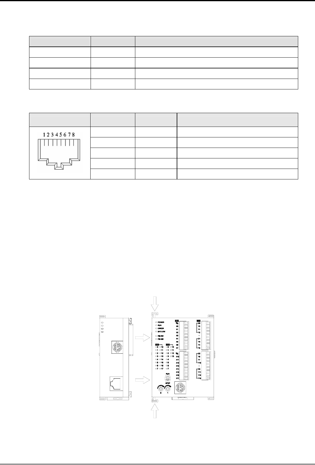
- 3 Installation & Wiring 7
- 4 Control Register (CR) 8
- 4.2 Explanations on CR 10
- 5 Setting up Software 16
- DVP-PLC Operation Manual 19
- 5.2 Basic Settings 22
- 5.3 Network Settings 23
- 5.4 Setting up E-Mails 26
- 5.5 Data Exchange 27
- 5.6 RTU 28
- 5.7 IP Filter 29
- 5.8 Static ARP Table 29
- 5.9 Setting up Password 30
- 6 Application Examples 32
- 6.5 IP Filter Protection 42
- 6.7 Application of E-Mail 46
- K7D0K49K100FROM 49
- 6.14 RTU Mapping 56
Related products and manuals for Computer Accessories Delta DVPEN01-SL
 (141 pages)
© 2020, manymanuals.com. All rights reserved. | 1.377 s |
 Manymanuals.com
 Manymanuals.de
 Manymanuals.fr
 Manymanuals.it
 Manymanuals.pl
 Manymanuals.cz
 Manymanuals.es
 Manymanuals-pt.com
Comments to this Manuals