Delta 16 SM600 Datasheet Page 13
- Page / 23
- Table of contents
- BOOKMARKS
- SM 6000 - se ries 1
- Safety Instructions 3
- Input Ratings 4
- Live Circuits 4
- Environmental Conditions 5
- DELTA ELEKTRONIKA BV SM6000 6
- DESCRIPTIONS 7
- PRO GRAMMING 8
- STATUS RE LAY OUT PUTS 9
- FUNC TION SWITCHES ON SW1 9
- RE MOTE SHUT DOWN (RSD) 10
- IN TER LOCK 10
- PRO GRAMMING SPEED 10
- PUL SATING LOAD 10
- IN SU LA TION 10
- SM6000 DELTA ELEKTRONIKA BV 11
- MASTER / SLAVE OP ER A TION 12
- SERIES OP ER A TION 12
- PAR AL LEL OP ER A TION 12
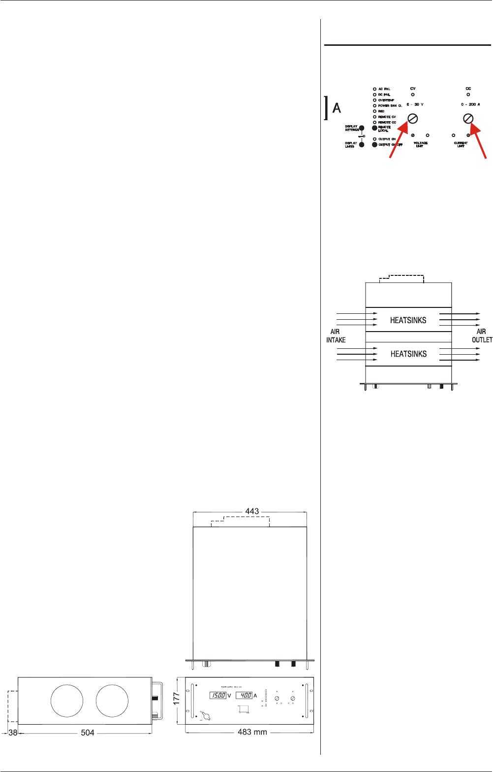
- VOLT AGE AND CUR RENT LIMIT 13
- DI MEN SIONS 13
- OPERATING MANUAL 14
- AN A LOG PRO GRAMMING 15
- IEEE488 / RS232 PRO GRAMMING 15
- MON I TORING OUT PUTS 15
- STATUS OUT PUTS 16
- RE MOTE SENSING 16
- BAT TERY CHARGER 16
- RE MOTE SHUTDOWN 16
- PRO GRAMMING VER SIONS: 17
- MAINTENANCE 18
- TROUBLE SHOOTING 19
- CALIBRATION 21
- DELTA ELEKTRONIKA B.V 23
Related products and manuals for Cordless chainsaws Delta 16 SM600
 (15 pages)
 (16 pages)
© 2020, manymanuals.com. All rights reserved. | 1.441 s |
 Manymanuals.com
 Manymanuals.de
 Manymanuals.fr
 Manymanuals.it
 Manymanuals.pl
 Manymanuals.cz
 Manymanuals.es
 Manymanuals-pt.com
Comments to this Manuals