DELTA ELEKTRONIKA BV SM6000
Page 4 - 3 OPERATING MAINTENANCE TROUBLE SHOOTING CALIBRATING July 2003, rev. March 2012
8) STATUS OUT PUTS
• The sta tus out puts have a sep a rate Ø con nec tion (pin 8) to avoid
un wanted off sets in the pro gram ming. This pin is pro tected with a
650 mA self re set ting fuse (F27_2 on P598).
9) RE MOTE SENSING
• Re move the links on the SENSE BLOCK (on rear panel) and con -
nect sense leads (thin shielded mea sur ing wires) to S+ and S–.
See fig 4 - 5 and fig. 4 - 6.
• With re mote sens ing the volt age on the load can be kept con stant.
The volt age drop in the load leads will be com pen sated. This fea -
ture is not rec om mended for nor mal use, be cause it can eas ily
give prob lems.
• Max. 2 V per load lead can be com pen sated. Note that the volt age
drop in the leads de creases the max. out put volt age rat ing. In fig.
4 - 7 it can be seen that on a 15 V power sup ply only 11 V will be
avail able on the load when 2x 2 V com pen sa tion is used.
• In or der to pre vent in ter fer ence it is ad vis able to twist the sense
leads. To min i mize the in duc tance in the load leads keep the
leads close to each other. The in duc tance of the loads leads could
give a prob lem with pul sat ing loads. In this case a large elec tro -
lytic ca pac i tor (Cd) in se ries with a damp ing re sis tor (Rd) both in
par al lel with the load will help (see fig. 4 - 6). Check that the ca -
pac i tor Cd in com bi na tion with the load leads and re sis tor Rd
forms a well damped cir cuit.
• Since the volt me ter is in ter nally con nected to the sens ing ter mi -
nals, it will au to mat i cally in di cate the volt age on the load. Note
that the volt age mea sured on the load will be lower than on the
out put ter mi nals.
• The Over Volt age Limit mea sures the volt age on the out put ter mi -
nals, so the OVL set ting should be in creased by the to tal volt age
drop in the load leads.
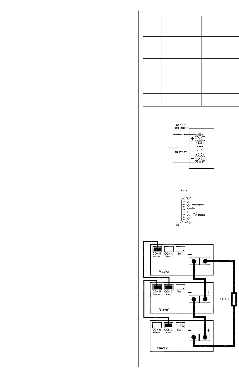
10) BAT TERY CHARGER
• The CV / CC reg u lated power sup plies are ideal bat tery charg ers.
Once the out put is set at the cor rect volt age the bat tery will charge
con stantly with out over charg ing. This can be use ful for emer -
gency power sys tems.
• Pro tec tive mea sures
Use a CIR CUIT BREAKER in se ries in or der to pro tect the power
sup ply from ac ci den tal re verse con nec tion (see fig. 4 - 8).The
cir cuit breaker should have a DC volt age rat ing twice the bat tery
volt age. Use the very fast type (Z), a type meant for pro tect ing
semi con duc tors (see ta ble 4 - 2).
The unit has a re verse di ode in par al lel with the out put, this di ode
and the wir ing can not with stand the thou sands of am peres sup -
plied by a wrongly con nected bat tery.
11) RE MOTE SHUTDOWN
• The Re mote ShutDown can be op er ated on CON E by a
volt age of +4 V...+12 V or by a re lay con tact be tween Vref and Re -
mote Shut Down (pin 9 and 5) (see fig. 4 - 9).
• When the unit is pro grammed with an op tional PSC, a
soft ware com mand can be used for Re mote Shut down.
• In the Re mote ShutDown con di tion, the RSD LED will light.
The DCF LED, DCF sta tus and the DCF re lay will be off.
Im por tant: If the link from the In ter lock con nec tor (CON A) has
been re moved, the RSD LED will be on, but in this con di tion also
the DCF LED, the DCF sta tus and the DCF re lay will be on.
12) MASTER / SLAVE SERIES OP ER A TION
• Con nect out put ter mi nals and test sys tem in nor mal
se ries op er a tion. En sure that all (out put) power con nec tions are
re li able.
• The volt age drop in the con nect ing leads be tween the units
should be kept < 10 mV.
• Switch off all units. Con nect units as shown in fig. 4 - 10.
To con nect the slaves with the mas ter via CON B and CON C, use
stan dard UTP ca bles (RJ45).
On all units put DIP switch 4 of SW1 in po si tion DOWN to set the
units in M/S se ries mode.
Sug gested cir cuit break ers for pro tec tion power sup ply
Model
Type num ber
Brand Re marks
SM15-400 HTI102 B 100
2pcs. needed
GE 4 poles par al lel
SM30-200 HTI102 B 100 GE 2 poles par al lel
SM45-140 HTI102 B 100 GE 2 poles par al lel
ex tra par al lel di ode on
out put needed
= OP TION 151
SM60-100 HTI101 B 100 GE no re marks
SM70-90 HTI101 B 100 GE no re marks
SM120-50 S281 UC-Z 50 ABB ex tra par al lel di ode on
out put needed
= OP TION 152
SM300-20 S282 UC-Z 20 ABB 2 poles in se ries
ex tra par al lel di odes on
out put needed
= OP TION 153
SM600-10 FHL 3603013
Schnei -
der
Elec tric
2 poles in se ries
ex tra par al lel di odes on
out put needed
ta ble 4 - 2 Cir cuit break ers for pro tec tion.
fig. 4 - 8
Charg ing bat tery with a cir cuit breaker in se ries
fig. 4 - 9 Re mote ShutDown with switch
fig. 4 - 10
Mas ter / Slave se ries con nec tion
 (15 pages)
 (16 pages)
 Manymanuals.com
 Manymanuals.de
 Manymanuals.fr
 Manymanuals.it
 Manymanuals.pl
 Manymanuals.cz
 Manymanuals.es
 Manymanuals-pt.com
Comments to this Manuals