Delta 22-470 User Manual
Browse online or download User Manual for Equipment Delta 22-470. Delta 22-470 User Manual
- Page / 28
- Table of contents
- BOOKMARKS
- 24" Planer 1
- TABLE OF CONTENTS 2
- IMPORTANT SAFETY INSTRUCTIONS 2
- CALIFORNIA PROPOSITION 65 3
- GENERAL SAFETY RULES 4
- SAVE THESE INSTRUCTIONS 5
- FUNCTIONAL DESCRIPTION 6
- CARTON CONTENTS 7
- ASSEMBLY 8
- ASSEMBLING CUTTERHEAD GUARD 9
- ASSEMBLING DUST HOOD 9
- ELECTRICAL CONNECTIONS 10
- OPERATION 11
- FEED ROLLER SPEEDS 12
- TABLE ROLLERS 13
- CHECKING AND ADJUSTING TABLE 14
- ROLLER HEIGHT 14
- BELT TENSION 15
- ANTI-KICKBACK FINGERS 15
- CHECKING AND ADJUSTING DRIVE 15
- CHECKING AND ADJUSTING FEED 16
- ROLLER BELT TENSION 16
- CHECKING, RESETTING 17
- AND REPLACING KNIVES 17
- CONSTRUCTING GAGE BLOCK 18
- ADJUSTING CHIPBREAKERS 18
- ADJUSTING PRESSURE BAR 19
- ADJUSTING INFEED ROLLER 20
- ADJUSTING OUTFEED ROLLER 20
- LEVELING THE TABLE 21
- ADJUSTING TABLE GIBS 22
- ADJUSTING TABLE HEIGHT SCALE 22
- TROUBLESHOOTING 23
- MAINTENANCE 23
- ACCESSORIES 24
- WARRANTY 25
- • DELTA SERVICE CENTERS 28
- • DELTA) 28
Summary of Contents
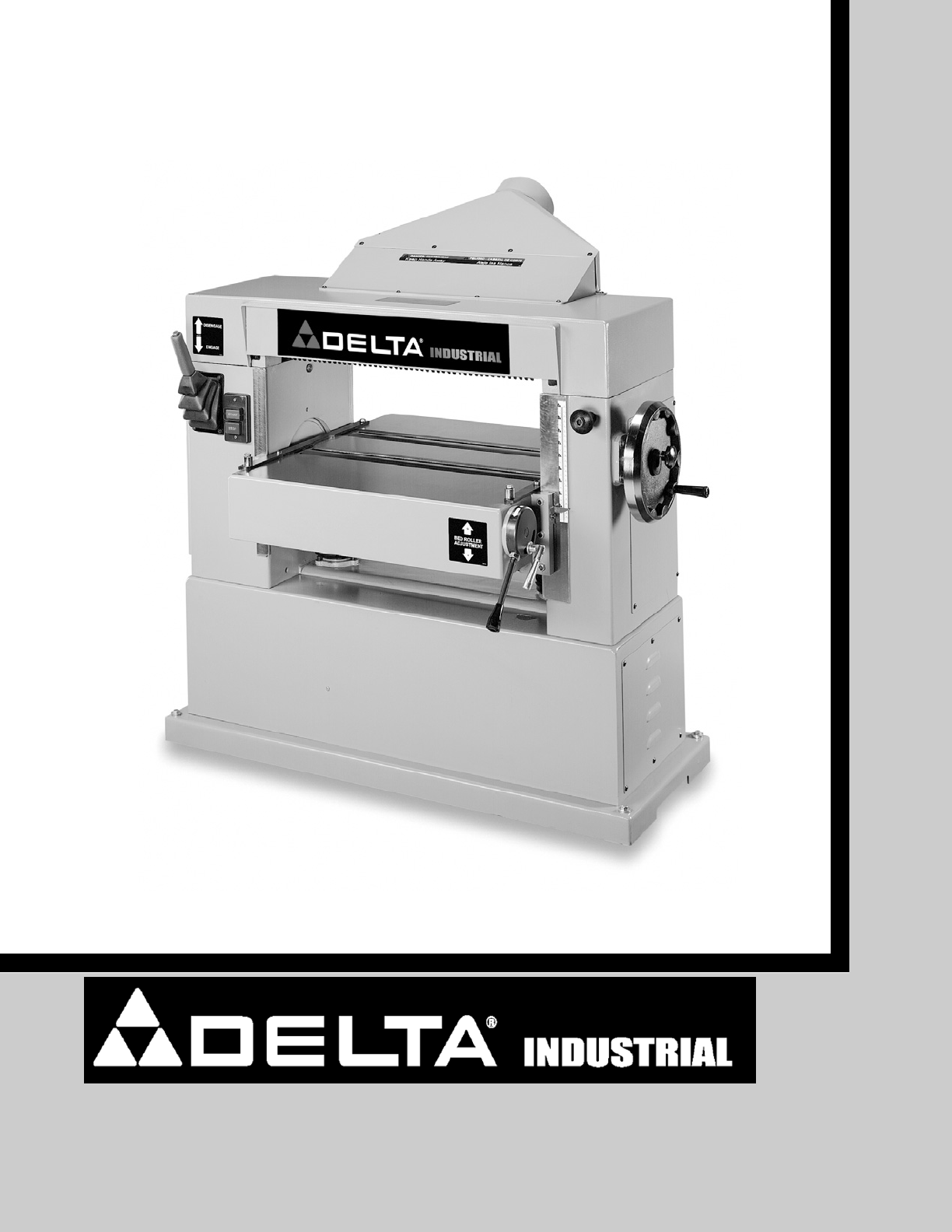
INSTRUCTION MANUALPART NO. 1342457 06-03-05Copyright © 2005 Delta Machinery24" Planer(Model 22-470, Three Phase)To learn more about DELTA MACHINE
10Fig. 12Fig. 11Fig. 10BADECGFKHMELECTRICAL CONNECTIONSThe planer comes wired for 220 volt operation, but it canbe wired for 440 volts. Before connect
11Fig. 13Fig. 15RAISING AND LOWERING THETABLEAdjust the table height by loosening lock knob (A) Fig.15, and rotating table adjusting handwheel (B). To
12FEED ROLLER SPEEDSYour planer is equipped with feed roller speeds of 20and 30 feet per minute depending on belt placement onthe pulleys. As a rule,
13Fig. 20Fig. 19Fig. 21TABLE ROLLERSYour planer is supplied with two table rollers (A) Fig. 21,which aid in feeding the stock by reducing friction be-
14Fig. 24 Fig. 25DEFABFig. 23ABCCHECKING AND ADJUSTING TABLEROLLER HEIGHTIt is not possible to give exact dimensions on the prop-er height setting of
15ANTI-KICKBACK FINGERSA series of anti-kickback fingers (A) Fig. 27, are providedon the infeed end of the planer to prevent kickback of theworkpiece
161. DISCONNECT THE MACHINE FROMTHE POWER SOURCE.2. Engage feed roller lever (D) Fig. 30.3. Remove four screws (E) Fig. 31, which hold engage-ment lev
17CHECKING, RESETTINGAND REPLACING KNIVESWhen checking, resetting and replacing knives, proceedas follows:1. DISCONNECT THE MACHINE FROMTHE POWER SOUR
18Fig. 36CONSTRUCTING GAGE BLOCKIn order to check and adjust the height of the chipbreaker,pressure bar, infeed and outfeed rollers and adjust the cut
19ADJUSTING PRESSURE BARThe pressure bar is located directly behind the cutterheadand rides on the planed surface of the stock, pressing thestock down
2TABLE OF CONTENTSRead and understand all warnings and operating instructions before using any tool or equipment. Whenusing tools or equipment, basic
201. DISCONNECT THE MACHINE FROMTHE POWER SOURCE.2. Make certain the knives are adjusted properly asexplained in section “CHECKING, ADJUSTINGAND REPLA
21Fig. 48Fig. 50LEVELING THE TABLEThe table is set parallel to the cutterhead at the factory andno further adjustment should be necessary. To check if
ADJUSTING TABLE GIBSIn the unlikely event of the table developing unwantedmovement during planing operations, the table can bechecked and adjusted as
23When using your machine, follow these few simple steps for achieving the best results.1. True Up One Face – Feed one face of the board over a jointe
24PARTS, SERVICE OR WARRANTY ASSISTANCEAll Delta Machines and accessories are manufactured to high quality standards and are serviced by a networkof P
25Two Year Limited New Product WarrantyDelta will repair or replace, at its expense and at its option, any new Delta machine, machine part, or machine
26NOTES
The following are trademarks of PORTER-CABLE •DELTA (Las siguientes son marcas registradas de PORTER-CABLE • DELTA S.A.) (Les marquessuivantes sont de
3Indicates an imminently hazardous situation which, if not avoided, will result in death or serious injury.Indicates a potentially hazardous situation
4GENERAL SAFETY RULESREAD AND UNDERSTAND ALL WARNINGS AND OPERATING INSTRUCTIONS BEFOREUSING THIS EQUIPMENT. Failure to follow all instructions listed
5ADDITIONAL SPECIFIC SAFETY RULESSAVE THESE INSTRUCTIONS. Refer to them often and use them to instruct others.1. DO NOT OPERATE THIS MACHINE until it
6A separate electrical circuit should be used for your machines. This circuit should not be less than #12 wire and shouldbe protected with a 20 Amp ti
7UNPACKING AND CLEANINGCarefully unpack the machine and all loose items from the shipping container(s). Remove the protective coating fromall unpainte
8ASSEMBLYASSEMBLY TOOLS REQUIREDASSEMBLY TIME ESTIMATE - 1-2 hours* M6 Allen wrench (supplied) * Flathead Screwdriver (Not Supplied* Forklift and Lift
9ASSEMBLING CUTTERHEAD GUARDPosition cutterhead guard (A) Fig. 7, on top cover of machine. Align holes in cutterhead guard (A) Fig. 7, with holes into
Related products and manuals for Equipment Delta 22-470


 (76 pages)
(60 pages)
(16 pages)
(76 pages)
(12 pages)
(54 pages)
(76 pages)
(60 pages)
(16 pages)
(76 pages)
(12 pages)
(54 pages)
© 2020, manymanuals.com. All rights reserved. | 0.406 s |
 Manymanuals.com
 Manymanuals.de
 Manymanuals.fr
 Manymanuals.it
 Manymanuals.pl
 Manymanuals.cz
 Manymanuals.es
 Manymanuals-pt.com
Comments to this Manuals