Delta 37-360 Instruction Manual Page 13
- Page / 24
- Table of contents
- BOOKMARKS
- DJ-30 12” Jointer 1
- GENERAL SAFETY RULES 2
- SAVE THESE INSTRUCTIONS 4
- Refer to them often 4
- POWER CONNECTIONS 5
- MOTOR SPECIFICATIONS 5
- GROUNDING INSTRUCTIONS 5
- EXTENSION CORDS 6
- FUNCTIONAL DESCRIPTION 6
- THREE PHASE OPERATION 6
- UNPACKING AND CLEANING 8
- REMOVING SHIPPING CRATE 8
- SELECTING FLOOR SPACE 9
- SINGLE PHASE INSTALLATION 11
- THREE PHASE INSTALLATION 12
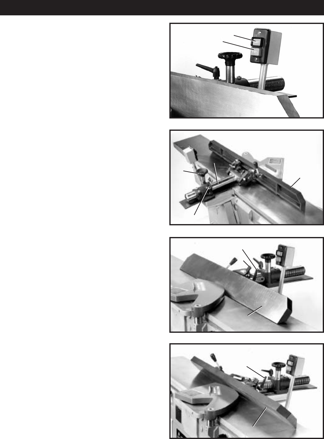
- START-STOP SWITCH 13
- FENCE OPERATION 13
- ADJUSTING FENCE 14
- POSITIVE STOPS 14
- INFEED TABLE 15
- ADJUSTMENTS 15
- OUTFEED TABLE 16
- ADJUSTING BELT TENSION 16
- ADJUSTING 17
- SPRING TENSION OF 17
- CUTTERHEAD GUARD 17
- OPERATION 18
- JOINTING AN EDGE 19
- PLANING OR SURFACING 19
- BEVELING 19
- TAPER CUTS 20
- CUTTING A RABBET 20
- DIRECTION OF GRAIN 20
- MAINTENANCE 21
- ACCESSORIES 23
- • DELTA SERVICE CENTERS 24
- • DELTA) 24
© 2020, manymanuals.com. All rights reserved. | 0.141 s |
 Manymanuals.com
 Manymanuals.de
 Manymanuals.fr
 Manymanuals.it
 Manymanuals.pl
 Manymanuals.cz
 Manymanuals.es
 Manymanuals-pt.com
Comments to this Manuals