Delta 36-L336 Use and Care Manual Page 11
- Page / 108
- Table of contents
- BOOKMARKS
- 36-L552LVC 1
- TABLE OF CONTENTS 2
- IMPORTANT SAFETY INSTRUCTIONS 2
- GENERAL SAFETY RULES 3
- SAVE THESE INSTRUCTIONS 4
- TERMINOLOGY 5
- MAKING A PUSH STICK 5
- KICKBACKS 5
- POWER CONNECTIONS 6
- MOTOR SPECIFICATIONS 6
- GROUNDING INSTRUCTIONS 6
- EXTENSION CORDS 7
- FUNCTIONAL DESCRIPTION 8
- CARTON CONTENTS 8
- UNPACKING AND CLEANING 9
- REMOVE SHIPPING FOAM 9
- ASSEMBLY 10
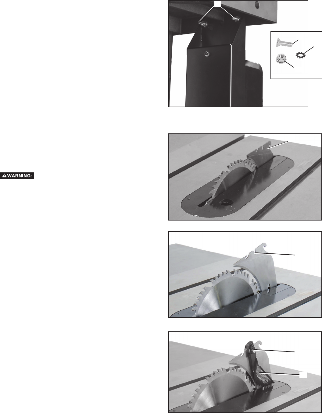
- BLADE GUARD ASSEMBLIES 11
- MITER GAUGE ASSEMBLY 12
- MITER GAUGE STORAGE 13
- DUST PORT REDUCER 13
- FENCE SYSTEM 13
- OPERATION 14
- TILTING THE BLADE 15
- THROAT PLATE ADJUSTMENT 15
- RIVING KNIFE OPERATION AND 15
- ADJUSTMENT 15
- SELECTING SAW BLADES 18
- RIVING KNIFE SELECTION 18
- ADJUSTING BLADE TILT SCALE 19
- If the blade tilt scale is 19
- , follow these steps: 19
- RELEASE CABLE 21
- CHANGING THE SAW BLADE 21
- ADJUSTING BELT TENSION 22
- BLADE GUARD OPERATION 22
- MACHINE USE 23
- RIPPING SMALL PIECES 24
- BEVEL RIPPING 25
- CROSSCUTTING 25
- BEVEL CROSSCUTTING 26
- MITERING 27
- MITER GAUGE OPERATION 27
- COMPOUND MITERING 27
- USING AN ACCESSORY DADO HEAD 27
- CHIPPERS 28
- OUTSIDE BLADE 28
- 3/4" (19 mm) 30
- 4-1/2" (114 mm) 30
- POWER TOOL INSTITUTE 31
- 1300 Sumner Avenue 31
- Cleveland, OH 44115-2851 31
- TROUBLESHOOTING 32
- MAINTENANCE 32
- REPLACING BELTS 33
- REPLACEMENT PARTS 34
- SERVICE AND REPAIRS 34
- ACCESSORIES 35
- WARRANTY 35
- PUSH STICK 36
- CONSERVER CES DIRECTIVES 37
- RÈGLES DE SÉCURITÉ GÉNÉRALES 38
- RACCORDEMENTS ÉLECTRIQUES 41
- SPÉCIFICATIONS DU MOTEUR 41
- CORDON DE RALLONGE 42
- DESCRIPTION FONCTIONNELLE 43
- CONTENUS DE BOITE 43
- DÉSEMBALLAGE ET NETTOYAGE 44
- RETRAIT DE LA MOUSSE 44
- D’EMBALLAGE 44
- ASSEMBLAGE 45
- INTERRUPTEUR 46
- MODULE ANTIRECUL, COUTEAU 46
- SÉPARATEUR ET ENSEMBLE 46
- PROTÈGE-LAME 46
- MODULE DU GUIDE D’ONGLET 47
- RÉDUCTEUR D’ORIFICE DE 48
- DÉPOUSSIÉRAGE 48
- SYSTÈME DE GUIDAGE 48
- RANGEMENT DU GUIDE D’ONGLET 48
- FONCTIONNEMENT 49
- INCLINAISON DE LA TABLE 50
- RÉGLAGE DU PASSE-LAME 50
- FONCTIONNEMENT ET RÉGLAGE DU 50
- COUTEAU SÉPARATEUR 50
- SÉLECTION DES LAMES DE SCIE 53
- LA LAME 54
- UTILISATION DU PROTÈGE-LAME 57
- UTILISATION DE LA MACHINE 58
- COUPES LONGITUDINALES 59
- TRONÇONNAGE 60
- SCIAGE SUR LE LONG EN BISEAU 60
- TRONÇONNAGE EN BISEAU 61
- UTILISATION DU GUIDE D’ONGLET 62
- ONGLET MIXTE 62
- ACCESSOIRE 62
- DÉCHIQUETEURS 63
- LAME EXTERNE 63
- 19 mm (3/4 po) 65
- 114 mm (4-1/2 po) 65
- POUSSOIR 66
- DEPANNAGE 67
- ENTRETIEN 67
- REMPLACEMET DES COURROIES 68
- PIÈCES DE RECHANGE 69
- ACCESSOIRIES 70
- GARANTIE 70
- GUARDE ESTAS INSTRUCCIONES 72
- NORMAS GENERALES DE SEGURIDAD 73
- TÉRMINOS 75
- FABRICANDO UNA VARA DE EMPUJE 75
- ESPECIFICACIONES DEL MOTOR 76
- CORDONES DE EXTENSIÓN 77
- DESCRIPCIÓN FUNCIONAL 78
- CONTENIDO DE CARTON 78
- DESEMPAQUETADO Y LIMPIEZA 79
- ENSAMBLAJE 80
- INTERRUPTOR 81
- PROTECTOR DE LA HOJA 81
- ENSAMBLAJE DEL CALIBRADOR DE 82
- RECOLECCIÓN DE POLVO 83
- SISTEMA DE GUÍA 83
- OPERACIÓN 84
- CÓMO INCLINAR LA HOJA 85
- VISTA DE LA PARTE 87
- POSTERIOR DE LA MESA 87
- SELECCIÓN DEL HENDEDOR 88
- 0 Y 45 GRADOS 89
- CÓMO AJUSTAR LA ESCALA DE 89
- INCLINACIÓN DE LA HOJA 89
- PARALELA A LA HOJA 90
- FUNCIONAMIENTO 92
- DEL PROTECTOR DE LA HOJA 92
- UTILIZAR LA MAQUINA 93
- CÓMO REALIZAR CORTES 94
- CORTE LONGITUDINAL 94
- RANURANDO PIEZAS PEQUEÑAS 95
- CORTE LONGITUDINAL CON BISEL 95
- CORTE TRANSVERSAL 95
- CORTE TRANSVERSAL CON BISEL 97
- CORTE CON INGLETES COMPUESTOS 98
- ZOCALADO 98
- ASTILLADORES 99
- HOJA EXTERNA 99
- 19 mm (3/4 pulg) 101
- 114 mm (4-1/2 pulg) 101
- LOCALIZACION DE FALLAS 102
- MANTENIMIENTO 102
- SERVICIO 104
- ACCESORIOS 105
- PÓLIZA DE GARANTÍA 105
- GARANTIA 106
- VARA PARA EMPUJAR 107
- (800) 223-7278 - U.S 108
- (800) 463-3582 - CANADA 108
- www.deltaportercable.com 108
- Copyright © 2009, 2010 DELTA 108
© 2020, manymanuals.com. All rights reserved. | 0.264 s |
 Manymanuals.com
 Manymanuals.de
 Manymanuals.fr
 Manymanuals.it
 Manymanuals.pl
 Manymanuals.cz
 Manymanuals.es
 Manymanuals-pt.com
Comments to this Manuals