Delta 31-392 User Manual Page 6
- Page / 16
- Table of contents
- BOOKMARKS
- 6" Edge Sander 1
- GENERAL SAFETY RULES 2
- SAVE THESE INSTRUCTIONS 3
- Refer to them often 3
- POWER CONNECTIONS 4
- MOTOR SPECIFICATIONS 4
- GROUNDING INSTRUCTIONS 4
- FUNCTIONAL DESCRIPTION 5
- EXTENSION CORDS 5
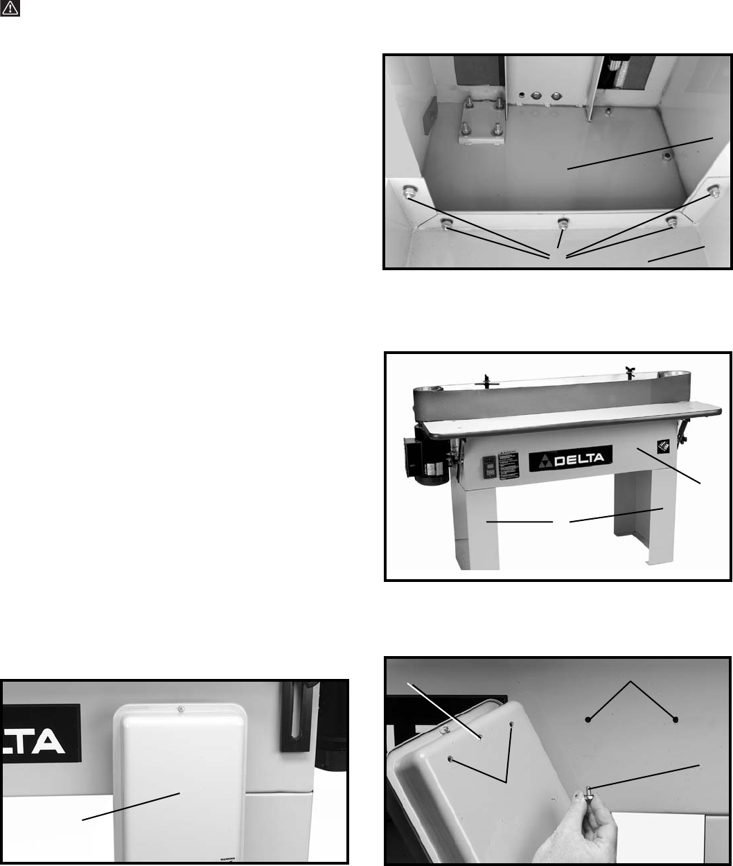
- ASSEMBLY 6
- ASSEMBLING BELT TENSION LEVER 7
- ASSEMBLING TOP GUARD AND 7
- DUST CHUTE ASSEMBLY 7
- ASSEMBLING AUXILIARY ABRASIVE 8
- DRUM AND SPINDLE ASSEMBLY TO 8
- DRIVE PULLEY 8
- STARTING AND STOPPING EDGE 10
- ADJUSTING TABLE POSITION 10
- ADJUSTING TILTING TABLE 10
- ADJUSTING SHORT PLATEN 10
- ADJUSTING LONG PLATEN 11
- ADJUSTING AUXILIARY END TABLE 11
- ADJUSTING BELT TRACKING 12
- ADJUSTING PULLEY ALIGNMENT 12
- OPERATIONS 13
- MAINTENANCE 14
- Two Year Limited Warranty 15
- • DELTA SERVICE CENTERS 16
- • DELTA) 16
Related products and manuals for Grinding machines Delta 31-392
 (12 pages)
 (68 pages)
© 2020, manymanuals.com. All rights reserved. | 0.753 s |
 Manymanuals.com
 Manymanuals.de
 Manymanuals.fr
 Manymanuals.it
 Manymanuals.pl
 Manymanuals.cz
 Manymanuals.es
 Manymanuals-pt.com
Comments to this Manuals