Delta 46-715 Instruction Manual
Browse online or download Instruction Manual for Lathes Delta 46-715. Delta 46-715 Instruction manual [en] User Manual
- Page / 24
- Table of contents
- TROUBLESHOOTING
- BOOKMARKS
- 14" Variable Speed 1
- Wood Lathe 1
- TABLE OF CONTENTS 2
- IMPORTANT SAFETY INSTRUCTIONS 2
- CALIFORNIA PROPOSITION 65 3
- GENERAL SAFETY RULES 4
- ADDITIONAL SAFETY RULES FOR 5
- WOOD LATHES 5
- GROUNDING INSTRUCTIONS 6
- EXTENSION CORDS 6
- FUNCTIONAL DESCRIPTION 7
- CARTON CONTENTS 7
- ASSEMBLY 7
- ASSEMBLING THE STAND 8
- HEADSTOCK SPUR CENTER 9
- TAILSTOCK LIVE CENTER 9
- TOOL REST 9
- OPERATION 10
- MACHINE USE 11
- HOW TO TURN SPINDLES 12
- CENTERING THE WORK 12
- MOUNTING THE WORK 12
- POSITION OF HANDS 13
- TOOL REST POSITION 13
- ROUGHING A CYLINDER 13
- SMOOTHING A CYLINDER 14
- USING THE PARTING TOOL 14
- SQUARING AN END 14
- CUTTING A SHOULDER 15
- CUTTING SMALL BEADS 15
- VEE GROOVES 16
- LONG CUTS 16
- COVE CUTS 16
- SQUARE SECTIONS 17
- FACEPLATE TURNING 17
- INBOARD/OUTBOARD TURNING 18
- MAINTENANCE 19
- TROUBLESHOOTING 19
- ACCESSORIES 21
- WARRANTY 22
- • DELTA SERVICE CENTERS 24
- • DELTA) 24
Summary of Contents
INSTRUCTION MANUALPART NO. 903742 - 03-18-05Copyright © 2005 Delta MachineryTo learn more about DELTA MACHINERY visit our website at: www.deltamachine
10ADJUSTING CLAMP ON TOOL RESTTo adjust the tool rest clamping action, use a 15/16" wrench to adjust the nut (A) Fig. 16 in the same manner as th
11ACTIVATING THE SPINDLEIMPORTANT: Unlock the spindle lock BEFORE operating the tool. The unlocked position is shown in Fig. 23A while the lockedposit
12HOW TO TURN SPINDLESSpindle turning is the principal type of wood turning (chair and table legs, lamp stems, etc.) The turning of spindles can be do
13TOOL REST POSITIONMount the tool rest in place about 1/8” away from the workand 1/8” above the work centerline (Fig. 32.) This position mayvary to
14SMOOTHING A CYLINDERTo smooth a cylinder, use a large skew chisel. This requirespractice, but experience with this tool is very important. Placethe
15CUTTING A SHOULDERUse the parting tool first to reduce the wood to within 1/16” ofthe required shoulder and diameter (Fig. 43). Clean the wastestock
16VEE GROOVESCutting the vee groove demands much the same technique asthe bead, except that the skew is hinged straight into the workwithout rotation
17Place the gouge on edge on the tool rest so that the grind ofthe chisel forms an approximate right angle with the work (Fig.57). The chisel contac
18MOUNTING THE WORKPIECE TO THE FACEPLATEFig. 63 shows direct mounting to the 3” faceplate along with attaching to the backing block. Because of the
198. Fig. 69 illustrates the rough cutting of the inside of a bowl.9. Outboard turning is illustrated in Fig. 70. Note that the headstock (A) is turne
2TABLE OF CONTENTSRead and understand all warnings and operating instructions before using any tool or equipment. Whenusing tools or equipment, basic
20PARTS, SERVICE OR WARRANTY ASSISTANCEAll Delta Machines and accessories are manufactured to high quality standards and are serviced by a networkof P
21A complete line of accessories is available from your Delta Supplier, Porter-Cable • Delta Factory Service Centers,and Delta Authorized Service Stat
22Two Year Limited New Product WarrantyDelta will repair or replace, at its expense and at its option, any new Delta machine, machine part, or machine
23NOTES
The following are trademarks of PORTER-CABLE •DELTA (Las siguientes son marcas registradas de PORTER-CABLE • DELTA S.A.) (Les marquessuivantes sont de
3Indicates an imminently hazardous situation which, if not avoided, will result in death or serious injury.Indicates a potentially hazardous situation
4GENERAL SAFETY RULESREAD AND UNDERSTAND ALL WARNINGS AND OPERATING INSTRUCTIONS BEFOREUSING THIS EQUIPMENT. Failure to follow all instructions listed
5ADDITIONAL SAFETY RULES FORWOOD LATHES1. DO NOT OPERATE THIS MACHINE UNTIL it isassembled and installed according to the instructions.2. OBTAIN ADVIC
6Fig. A Fig. BGROUNDED OUTLET BOXCURRENTCARRYINGPRONGSGROUNDING BLADEIS LONGEST OF THE 3 BLADESGROUNDED OUTLET BOXGROUNDINGMEANSADAPTER2. Grounded, co
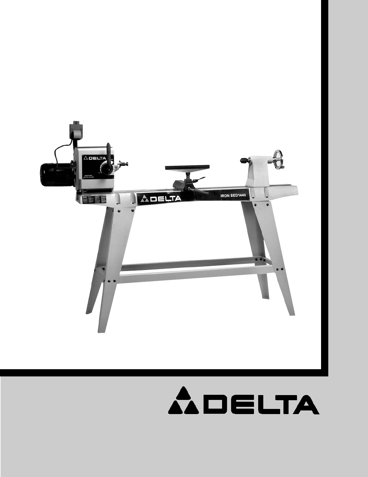
7FOREWORDFUNCTIONAL DESCRIPTIONNOTICE: The photo on the manual cover illustrates the current production model. All other illustrations contained inthe
8ASSEMBLING THE STAND1. Attach the two long tie bars (A) Fig. 3 (with the flanges up)to the center of each stand leg (B) by using eight carriagebolts
9HEADSTOCK SPUR CENTERThe 46-715 comes with a faceplate attached. Before inserting the spur center in the spindle,remove this faceplate. Insert the kn
More documents for Lathes Delta 46-715

Related products and manuals for Lathes Delta 46-715


 (8 pages)
(23 pages)
(2 pages)
(8 pages)
(23 pages)
(2 pages)
© 2020, manymanuals.com. All rights reserved. | 0.149 s |
 Manymanuals.com
 Manymanuals.de
 Manymanuals.fr
 Manymanuals.it
 Manymanuals.pl
 Manymanuals.cz
 Manymanuals.es
 Manymanuals-pt.com
Comments to this Manuals