Delta 46-745 Instruction Manual
Browse online or download Instruction Manual for Lathes Delta 46-745. Delta 46-745 Instruction manual [en] User Manual
- Page / 24
- Table of contents
- BOOKMARKS
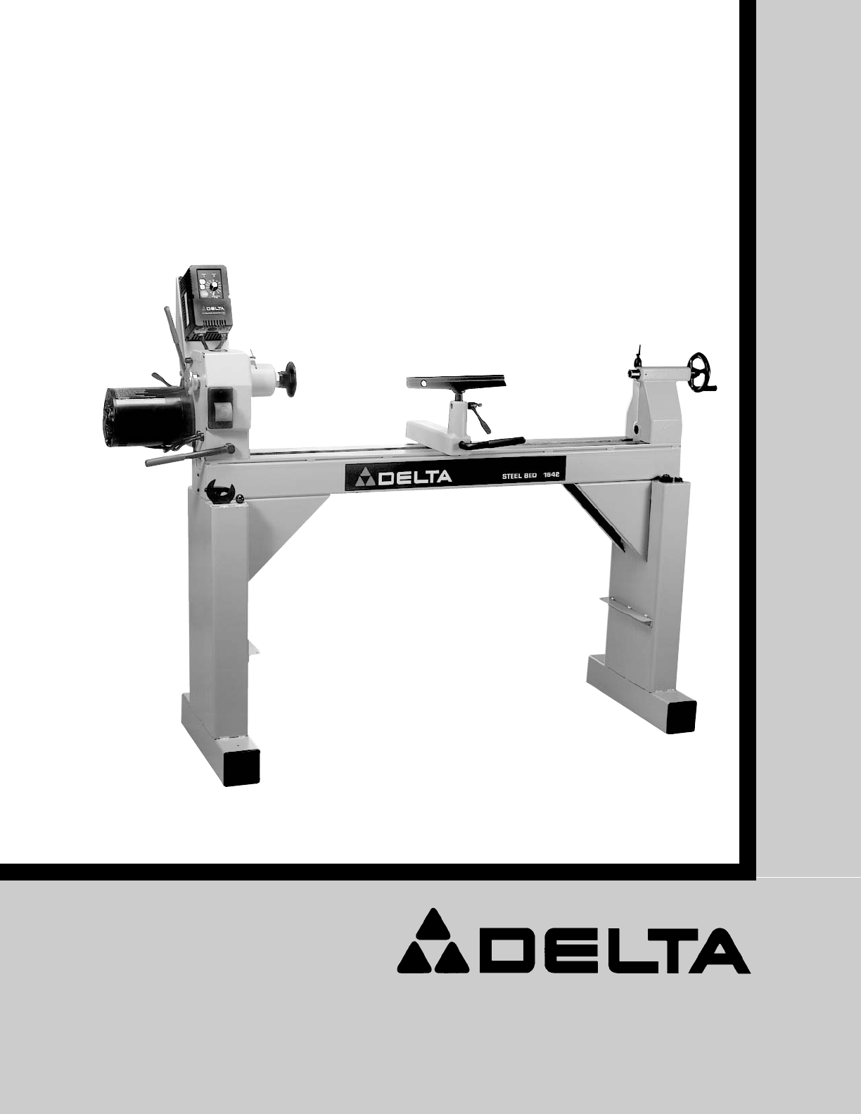
- 16” Variable Speed 1
- Wood Lathe 1
- GENERAL SAFETY RULES 2
- 03-17-03 3
- SAVE THESE INSTRUCTIONS 4
- POWER CONNECTIONS 5
- MOTOR SPECIFICATIONS 5
- GROUNDING INSTRUCTIONS 5
- EXTENSION CORDS 6
- FUNCTIONAL DESCRIPTION 7
- ASSEMBLY 8
- ATTACHING LEG INSERTS 9
- HEADSTOCK SPUR CENTER 9
- STARTING AND STOPPING THE 11
- LOCKING SWITCH IN THE 11
- “OFF” POSITION 11
- ACTIVATING THE SPINDLE 11
- CHANGING SPEED RANGES 12
- OPERATION 13
- MOUNTING THE WORK 14
- TOOL REST POSITION 14
- ROUGHING A CYLINDER 15
- POSITION OF HANDS 15
- SMOOTHING A CYLINDER 16
- USING THE PARTING TOOL 16
- SQUARING AN END 16
- CUTTING A SHOULDER 17
- CUTTING SMALL BEADS 17
- VEE GROOVES 18
- LONG CUTS 18
- COVE CUTS 18
- SQUARE SECTIONS 19
- FACEPLATE TURNING 20
- MOUNTING WORK TO FACEPLATE 20
- OUTBOARD TURNING 20
- MAINTENANCE 21
- LUBRICATION 22
- ACCESSORIES 23
- • DELTA SERVICE CENTERS 24
- • DELTA) 24
Summary of Contents
INSTRUCTION MANUALTo learn more about DELTA MACHINERY visit our website at: www.deltamachinery.com.For Parts, Service, Warranty or other Assistance,pl
10Fig. 14DBFig. 16ACTAILSTOCK LIVE CENTERThe tailstock live center (A) Fig. 14, supplied with yourlathe, is equipped with a No. 2 Morse Taper shank.NO
11Fig. 19Fig. 20CABFig. 18STARTING AND STOPPING THETOOLThe switch (A) Fig. 18 provides electrical power to theadjustable speed drive. Lift the safety
12Fig. 24ABFig. 23AECDFig. 25F6. The REVERSE (REV) button is used FOR SANDINGPURPOSES ONLY. NOTE: When using the faceplate, becertain that the facepla
13LATHE TOOLSStandard wood turning tools come in several differentconfigurations (Fig. 26). The majority of turnings willrequire the gouge tool (A) Fi
14Fig. 29Fig. 30TOOL REST POSITIONMount the tool rest in place about 1/8” away fromthe work and 1/8” above the work centerline (Fig. 32.)This position
15Fig. 33Fig. 34Fig. 35ROUGHING A CYLINDERThe large gouge is used in the first turning operation bysmoothing the sharp corners of the work. Run the la
16SMOOTHING A CYLINDERTo smooth a cylinder, use a large skew chisel. Thisrequires practice, but experience with this tool is veryimportant. Place the
17CUTTING A SHOULDERUse the parting tool first to reduce the wood to within1/16” of the required shoulder and diameter (Fig. 43).Clean the waste stock
18VEE GROOVESCutting the vee groove demands much the sametechnique as the bead, except the skew is hingedstraight into the work without rotation (Fig.
19The gouge is placed on edge on the tool rest so that thegrind of the chisel forms an approximate right anglewith the work (Figs. 57). The chisel con
2Indicates an imminently hazardous situation which, if not avoided, will result in death or serious injury.Indicates a potentially hazardous situation
20FACEPLATE TURNINGMount turnings that cannot be worked between centers on a faceplate. The greater part of thistype of turning is done with the facep
21MAINTENANCEFig. 71REPLACING DRIVE BELT1. Use the supplied Allen wrench (A) Fig. 71 to loosen the set screw in the handwheel (B) Fig. 71. Engage s
Use a light oil to lubricate eccentric (A) Fig. 79, and pivot points (B) on both the headstock and the tailstock. (Tailstockillustrated).Use the tip o
23A complete line of accessories is available from your Delta Supplier, Porter-Cable • Delta Factory Service Centers,and Delta Authorized Service Stat
The following are trademarks of PORTER-CABLE·DELTA (Las siguientes son marcas registradas de PORTER-CABLE S.A.): Auto-Set®, BAM-MER®, B.O.S.S.®, Build
31. FOR YOUR OWN SAFETY, READ THE INSTRUC-TION MANUAL BEFORE OPERATING THEMACHINE. Learning the machine’s application,limitations, and specific hazard
4FAILURE TO FOLLOW THESE RULES MAY RESULT IN SERIOUS PERSONAL INJURY.ADDITIONAL SAFETY RULES FOR WOOD LATHES 1. DO NOT OPERATE THIS MACHINE UNTIL it i
5A separate electrical circuit should be used for your machines. This circuit should not be less than #12 wire and shouldbe protected with a 20 Amp ti
6Use proper extension cords. Make sure your extension cord is in good condition and is a 3-wire exten-sion cord which has a 3-prong grounding type plu
7Carefully unpack the tool and all loose items from the shipping container(s). Remove the protective coating from allunpainted surfaces. This coating
8Fig. 7Fig. 8ABBACFig. 6The hole in the pedestal (C) Fig.6 can be used to fill thepedestal with sand or concrete to provide more ballast.NOTE: If sand
9Fig. 10ATTACHING LEG INSERTSThe lathe is supplied with four leg inserts, one of whichis shown (A) Fig. 10. To attach the leg inserts to the pedestals
Related products and manuals for Lathes Delta 46-745
 (24 pages)

 (64 pages)
(24 pages)
(64 pages)
(24 pages)
 (8 pages)
(23 pages)
(2 pages)
(8 pages)
(23 pages)
(2 pages)
© 2020, manymanuals.com. All rights reserved. | 0.860 s |
 Manymanuals.com
 Manymanuals.de
 Manymanuals.fr
 Manymanuals.it
 Manymanuals.pl
 Manymanuals.cz
 Manymanuals.es
 Manymanuals-pt.com
Comments to this Manuals