Delta 36-220 Service Manual
Browse online or download Service Manual for Mitre saws Delta 36-220. Delta 36-220 Technical data User Manual
- Page / 35
- Table of contents
- BOOKMARKS
- POWER TOOLS 1
- COMPOUND SAW 1
- 1. PRODUCT NAME 4
- 2. MARKETING OBJECTIVE 4
- 3. APPLICATIONS 4
- 4. SELLING POINTS 4
- 45 right and 5
- to either the left or right 6
- 5. SPECIFICATIONS 7
- 9. ADJUSTMENT OF COMPONENTS 14
- 10. PACKING 14
- 12. REPAIR GUIDE 25
- Work Flow 29
- --- 27 30
- Assembly Diagram for C 10FC2 30
- HOLDER ASS'Y 31
- MOTOR ASS'Y 31
- --- 29 32
- --- 30 33
- --- 31 34
- --- 32 35
Summary of Contents
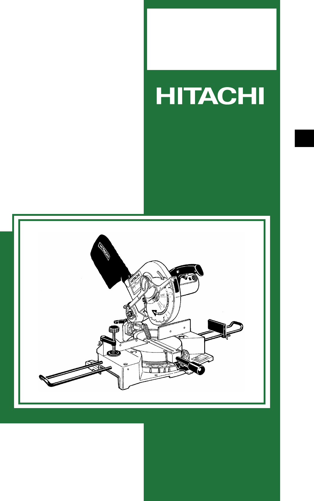
POWER TOOLSTECHNICAL DATAANDSERVICE MANUALCOMPOUND SAWC 10FC2SPECIFICATIONS AND PARTS ARE SUBJECT TO CHANGE FOR IMPROVEMENTLIST No. E927 May
--- 7 ---CAUTION For safe operation, see instruction manual. Do not expose to rain or use in damp locations.(1) Precautions on the Name PlateEach Mode
--- 8 ---8. ADJUSTMENT AND OPERATIONAL PRECAUTIONS8-1. Confirmation of Saw Blade Lower Limit PositioningThe lower limit of the saw blade cutting depth
--- 9 ---8-3. Cutting Operation(1) Cutting efficiency will be reduced if a dull saw blade is used, if an excessively long extension cord id used, or i
--- 10 ---(6) Compound (miter + bevel) cuttingCompound cutting can be accomplished by combining the miter cutting and bevel cutting operations descri
--- 11 ---9. ADJUSTMENT OF COMPONENTS9-1. Bevel Angle AdjustmentWhen shipped from the factory, the heights of 6 mmbolt (A) and 6 mm bolt (B) are adjus
--- 12 ---11. PRECAUTIONS IN DISASSEMBLY AND REASSEMBLY11-1. DisassemblySpecial attention in disassembly should be given to the following items.The ci
--- 13 ---1. Remove the two Tapping Screws (W/Washers) D5 x 20 [95] at theright and the two Machine Screws M4 x 20 [100]. Remove theHandle (Right) [
--- 14 ---1. Remove the two Machine Screws (W/Washer) M5 x 14 [39] andthe Chip Deflector [40] (debris guard).2. Remove the two Hex. Bolts (W/Washers)
--- 15 ---ItemNo.DisassemblyspotsDisassembly procedure Necessary tools4 TableBase6559586365666267607164Fig. 15PhillipsScrewdriver13 mm boxwrench616872
--- 16 ---1. Disassembly of the Armature Ass'y(1) Remove the two Brush Caps [136] and the two Carbon Brushes[135].(2) Remove the four Tapping Scr
REMARK:Throughout this TECHNICAL DATA AND SERVICE MANUAL, a symbol(s)is(are) used in the place of company name(s) and model name(s)
--- 17 ---3. Disassembly of the Spindle Ass'y Remove the Spindle Ass'y [111] by gently tapping the Arm [120]with a plastic hammer.ItemNo.
--- 18 ---11-2. ReassemblyReassembly can be accomplished by following the disassembly procedures in reverse. However, specialattention should be give
--- 19 ---11-3. Wiring DiagramCarefully ensure that wiring is accomplished as illustrated below. As incorrect wiring will result in lack of rotation,
--- 20 ---11-5. No-load CurrentAfter no-load operation for 30 minutes, the no-load current values should be as follows.Voltage, FreauencyNo-load curre
--- 21 ---(4) Reassembly of the Table [60]When reassembling the Table [60] and the Base [74], tighten the Chuck Nut M8 [58] so that the Table [60]turn
--- 22 ---12. REPAIR GUIDEItemPhenomenon Cause (s)Inspection • Repair • Adjustment1 Inaccurate cutting...Inaccurate spuareness of cut surface...Cut
--- 23 ---ItemPhenomenon Cause (s)Inspection • Repair • Adjustment1 g Excessivemisalignment of thebase and the tablecauses the saw bladeto cut into t
--- 24 ---ItemPhenomenon Cause (s)Inspection • Repair • Adjustment d Excessively fastcutting speedFactorystandard---Reduce cutting speed. e Improper
--- 25 ---ItemPhenomenon Cause (s)Inspection • Repair • Adjustment a The power cord isnot connected topower supply.Factorystandard---Check power supp
--- 26 ---11. STANDARD REPAIR TIME (UNIT) SCHEDULESMODEL 10 20 30 40FixedVariableC 10FC2Work FlowHandleSwitchGeneral AssemblyFixed CostLinkBlade Guard
PageCONTENTS[ Business Section ]1. PRODUCT NAME•••••••••••••••••••••••••••••••••••••••••••••••••••••••••••••••••••••••••••••••••••••••••••••••••••••••
--- 27 ---Assembly Diagram for C 10FC2
--- 28 ---C 10FC2MOTOR ASS'YHOLDER ASS'Y
--- 29 ---PARTSC 10FC2ITEMNo.CODE NO. DESCRIPTIONNO.USEDREMARKS1 311-024 TRUSS HD. SCREW 1/4''X1/2'' 12 311-025 LINK 13 317-345 MA
--- 30 ---PARTSC 10FC2: ALTERNATIVE PARTSITEMNo.CODE NO. DESCRIPTIONNO.USEDREMARKS52 311-129 HEX. SOCKET SET SCREW M6X12 153 311-065 PIVOT SHAFT 154 9
--- 31 ---PARTSC 10FC2ITEMNO.CODE NO. DESCRIPTIONNO.USEDREMARKS102 317-382 VISE ASS’Y 1 INCLUD.103-110103 967-079 HEX. SOCKET SET SCREW M6X8 1104 311-
--- 32 ---: ALTERNATIVE PARTSC 10FC2ITEMNO.CODE NO. DESCRIPTIONNO.USEDREMARKS901 976-472TCT SAW BLADE CROSS-CUT 255MM-D15.9 HOLE1902 977-671TCT SAW BL
--- 1 ---1. PRODUCT NAMEHitachi Compound Saw, Model C 10FC22. MARKETING OBJECTIVEThe Model C 10FC2 was developed to upgrade and replace the current Mo
--- 2 ---4-1. Selling Point Descriptions(1) Press cuttingMakermodelMax. cuttingdimensionHeight x Width(H x W)HITACHIC 10FC267 x 146(2-5/8" x 5-3/
--- 3 ---MakermodelMax. cuttingdimensionLeft bevel 45Right/Left miter 45Height x Width(H x W)HITACHIC 10FC244 x 89(1-3/4" x 3-1/2")By turnin
--- 4 ---5. SPECIFICATIONSMaximumcuttingdimensionsHeight xWidth(H x W)0 (Right angle)Miter right/left 45Bevel left 45Miter right/left 45+Bevel left 4
--- 5 ---6. COMPARISONS WITH SIMILAR PRODUCTSItemMaker/ModelMax.cuttingdimensionsHeightx Width(H x W)0 (Right angle)67 mm x 146 mm(2-5/8" x 5-3/
--- 6 ---ItemMaker/ModelStandard accessories 255 mm (10") TCTsaw blade (24 teeth)for wood andaluminum cutting Dust bag Vise ass'y WrenchHITA
Related products and manuals for Mitre saws Delta 36-220
 (25 pages)

 (52 pages)
(15 pages)
(21 pages)
(25 pages)
(23 pages)
(28 pages)
(32 pages)
(17 pages)
(28 pages)
(23 pages)
(52 pages)
(15 pages)
(21 pages)
(25 pages)
(23 pages)
(28 pages)
(32 pages)
(17 pages)
(28 pages)
(23 pages)
© 2020, manymanuals.com. All rights reserved. | 1.192 s |
 Manymanuals.com
 Manymanuals.de
 Manymanuals.fr
 Manymanuals.it
 Manymanuals.pl
 Manymanuals.cz
 Manymanuals.es
 Manymanuals-pt.com
Comments to this Manuals