Delta 36-255L Instruction Manual Page 14
- Page / 25
- Table of contents
- TROUBLESHOOTING
- BOOKMARKS
- INSTRUCTION MANUAL 1
- TABLE OF CONTENTS 2
- IMPORTANT SAFETY INSTRUCTIONS 2
- CALIFORNIA PROPOSITION 65 3
- GENERAL SAFETY RULES 4
- POWER CONNECTIONS 6
- MOTOR SPECIFICATIONS 6
- GROUNDING INSTRUCTIONS 6
- FUNCTIONAL DESCRIPTION 7
- ASSEMBLY 8
- CARTON CONTENTS 8
- POSITION 9
- ATTACHING EXTENSION TABLE AND 9
- FENCE SLIDE 9
- ATTACHING DUST BAG 10
- OPERATION 11
- ADJUSTING SLIDING FIT BETWEEN 12
- MOVABLE TABLE AND BASE 12
- ROTATING THE TABLE 12
- FOR MITER SAW CUTTING 12
- ADJUSTING FENCE 90° TO BLADE 13
- TABLE HAZARD ZONE 13
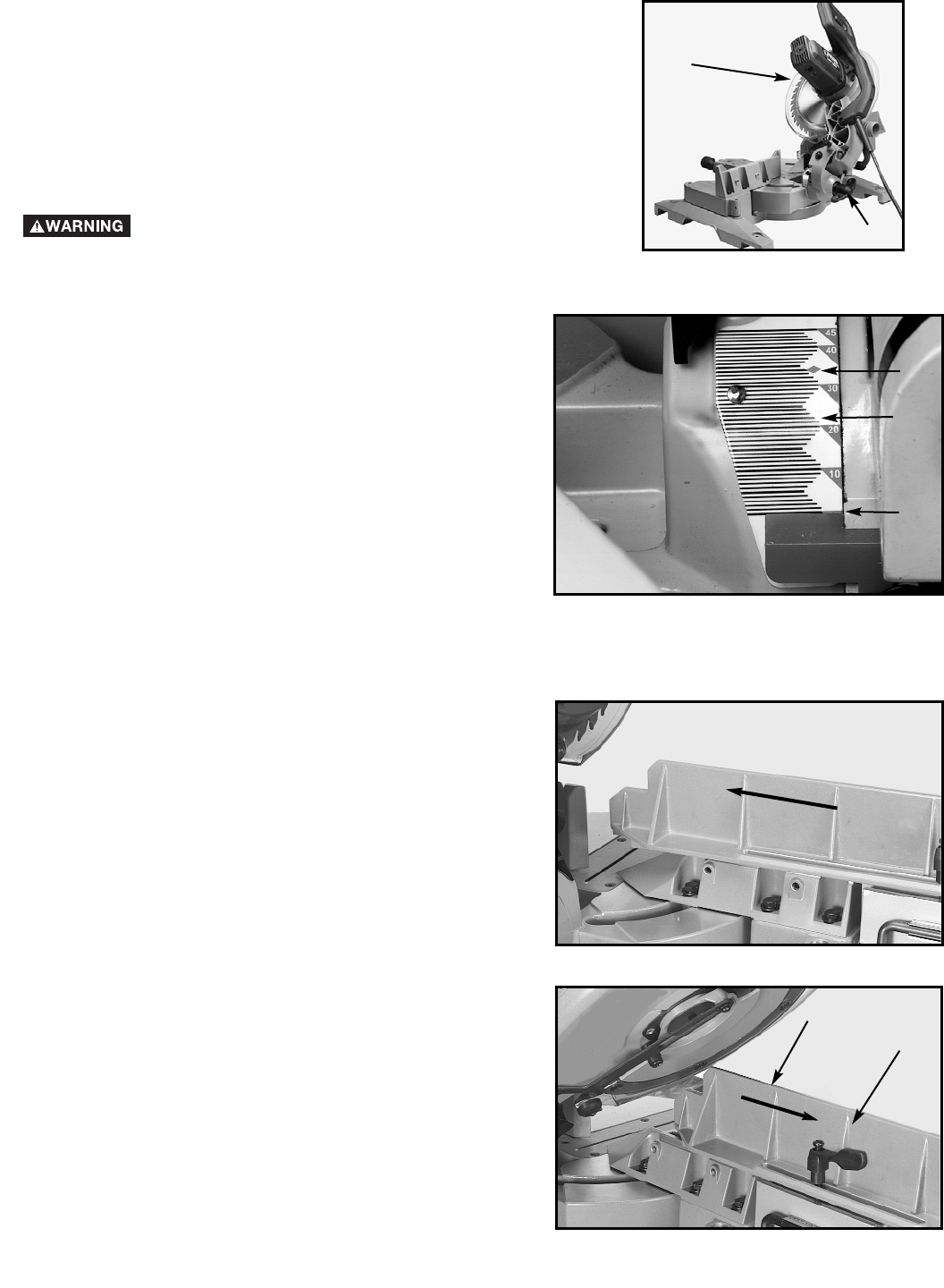
- TILTING CUTTINGHEAD FOR BEVEL 14
- ADJUSTING SLIDING FENCE 14
- ADJUSTING CHIP DEFLECTOR 15
- LASER USE AND ADJUSTMENTS 17
- MACHINE USE 19
- WORK SUPPORT EXTENSIONS 20
- CUTTING CROWN MOULDING 21
- 45-45 CROWN MOULDING 21
- OTHER ANGLES 21
- MAINTENANCE 22
- TROUBLESHOOTING 22
- ACCESSORIES 23
- WARRANTY 23
- • DELTA SERVICE CENTERS 25
- • DELTA) 25
Related products and manuals for Mitre saws Delta 36-255L
 (23 pages)
(28 pages)
(32 pages)
(17 pages)
(28 pages)
(23 pages)
(23 pages)
(28 pages)
(32 pages)
(17 pages)
(28 pages)
(23 pages)
© 2020, manymanuals.com. All rights reserved. | 0.226 s |
 Manymanuals.com
 Manymanuals.de
 Manymanuals.fr
 Manymanuals.it
 Manymanuals.pl
 Manymanuals.cz
 Manymanuals.es
 Manymanuals-pt.com
Comments to this Manuals