Delta 36-312 Instruction Manual Page 8
- Page / 17
- Table of contents
- BOOKMARKS
- Miter Saw 1
- GENERAL SAFETY RULES 2
- SAVE THESE INSTRUCTIONS 4
- POWER CONNECTIONS 5
- MOTOR SPECIFICATIONS 5
- UNPACKING 5
- EXTENSION CORDS 5
- ASSEMBLY 6
- AND OPERATION 6
- FUNCTIONAL DESCRIPTION 6
- CARTON CONTENTS 6
- OPERATION AND ADJUSTMENTS 7
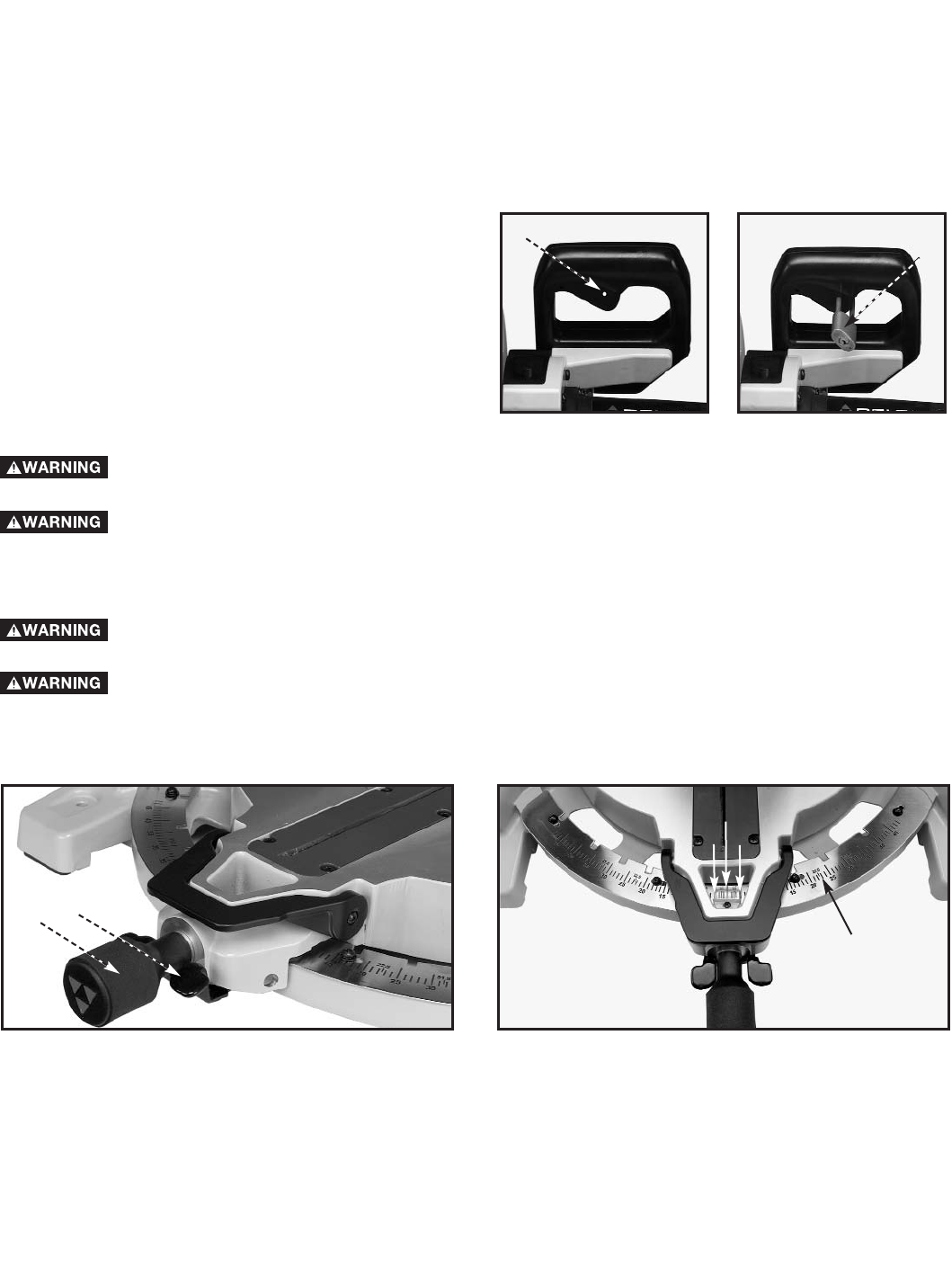
- STARTING AND STOPPING MACHINE 8
- ADJUSTING FENCE 90° TO BLADE 9
- TABLE HAZARD ZONE 9
- ADJUSTING SLIDING FIT BETWEEN 11
- CUTTINGHEAD ARM AND TRUNNION 11
- ADJUSTING THE BEVEL LOCK 11
- AUXILIARY WOOD FENCE 12
- CUTTING ALUMINUM 12
- ADJUSTING LOWER BLADE GUARD 12
- CUTTING CROWN MOULDING 13
- MAINTENANCE 14
- ACCESSORIES 15
- • DELTA SERVICE CENTERS 17
- • DELTA) 17
Related products and manuals for Mitre saws Delta 36-312
 (28 pages)
(23 pages)
(28 pages)
(23 pages)
© 2020, manymanuals.com. All rights reserved. | 1.621 s |
 Manymanuals.com
 Manymanuals.de
 Manymanuals.fr
 Manymanuals.it
 Manymanuals.pl
 Manymanuals.cz
 Manymanuals.es
 Manymanuals-pt.com
Comments to this Manuals