Delta DP350 Instruction Manual Page 12
- Page / 44
- Table of contents
- BOOKMARKS
- Instruction Manual 1
- Manuel d’utilisation 1
- Manual de instrucciones 1
- TABLE OF CONTENTS 2
- IMPORTANT SAFETY INSTRUCTIONS 2
- GENERAL SAFETY RULES 3
- SAVE THESE INSTRUCTIONS 3
- POWER CONNECTIONS 5
- MOTOR SPECIFICATIONS 5
- GROUNDING INSTRUCTIONS 5
- FUNCTIONAL DESCRIPTION 6
- CARTON CONTENTS 6
- ASSEMBLY 7
- Fig. 7 Fig. 8 8
- OPERATION 10
- ADJUSTING THE TABLE 11
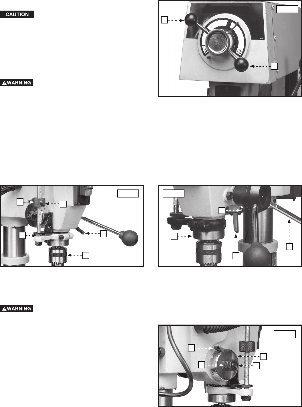
- QUILL ADJUSTMENTS 12
- VARIABLE SPEED CONTROL 12
- DRILLING HOLES TO DEPTH 12
- MACHINE USE 13
- TROUBLESHOOTING 14
- MAINTENANCE 14
- ACCESSORIES 15
- WARRANTY 15
- CONSERVEZ CES INSTRUCTIONS! 16
- RÈGLES DE SÉCURITÉ GÉNÉRALES 17
- CONSERVER CES DIRECTIVES 18
- RACCORDEMENTS ÉLECTRIQUES 19
- SPÉCIFICATIONS DU MOTEUR 19
- DESCRIPTION FONCTIONNELLE 20
- CONTENUS DE BOITE 20
- ASSEMBLAGE 21
- FONCTIONNEMENT 24
- AJUSTEMENT DE LA TABLE 25
- RÉGLAGES DU FOURREAU 26
- UTILISATION DE LA MACHINE 27
- ENTRETIEN 28
- DEPANNAGE 28
- ACCESSOIRIES 29
- GARANTIE 29
- PROPOSICIÓN DE CALIFORNIA 65 30
- NORMAS GENERALES DE SEGURIDAD 31
- GUARDE ESTAS INSTRUCCIONES 32
- ESPECIFICACIONES DEL MOTOR 33
- DESCRIPCIÓN FUNCIONAL 34
- CONTENIDO DE CARTON 34
- ENSAMBLAJE 35
- OPERACIÓN 38
- AJUSTE DEL BANCO 39
- AJUSTES AL EJE HUECO 40
- CONTROL DE VELOCIDAD VARIABLE 40
- UTILIZAR LA MAQUINA 41
- MANTENIMIENTO 42
- LOCALIZACION DE FALLAS 42
- SERVICIO 42
- ACCESORIOS 43
- GARANTIA 43
- PÓLIZA DE GARANTÍA 43
- Delta Machinery 44
- 4825 Highway 45 North 44
- Jackson, TN 38305 44
- (800) 223-7278 44
Related products and manuals for Power drills Delta DP350


 (20 pages)
 (68 pages)
© 2020, manymanuals.com. All rights reserved. | 0.721 s |
 Manymanuals.com
 Manymanuals.de
 Manymanuals.fr
 Manymanuals.it
 Manymanuals.pl
 Manymanuals.cz
 Manymanuals.es
 Manymanuals-pt.com
Comments to this Manuals