Delta TP400LS Instruction Manual
Browse online or download Instruction Manual for Power planers Delta TP400LS. Delta TP400LS Instruction manual User Manual
- Page / 21
- Table of contents
- BOOKMARKS
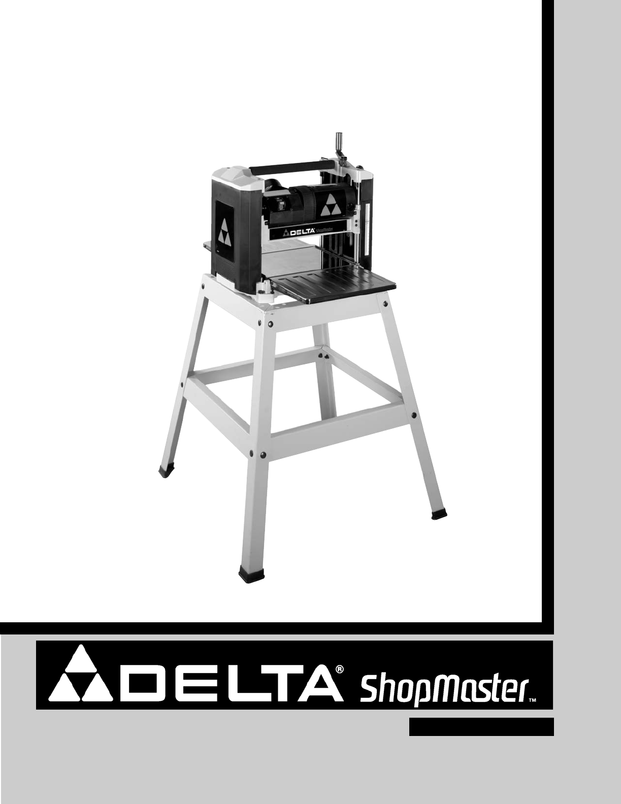
- 12½" Portable Planer 1
- GENERAL SAFETY RULES 2
- SAVE THESE INSTRUCTIONS 4
- Refer to them often 4
- POWER CONNECTIONS 5
- MOTOR SPECIFICATIONS 5
- GROUNDING INSTRUCTIONS 5
- EXTENSION CORDS 6
- FUNCTIONAL DESCRIPTION 7
- UNPACKING AND CLEANING 7
- PLANER PARTS 8
- ASSEMBLY 8
- FASTENING PLANER TO STAND 10
- RECOMMENDED 12
- DEPTH OF CUT 12
- LEVELING 12
- TABLE EXTENSIONS 12
- KNIFE TRANSFER TOOL 13
- WRENCH STORAGE 13
- REPLACING KNIVES 14
- ADJUSTING HEIGHT 16
- OF OUTFEED ROLLER 16
- OPERATION 17
- MAINTENANCE 18
- BRUSH INSPECTION 18
- AND REPLACEMENT 18
- LUBRICATION 18
- ACCESSORIES 20
- • DELTA SERVICE CENTERS 21
- • DELTA) 21
Summary of Contents
INSTRUCTION MANUAL12½" Portable Planer(Model TP400LS)PART NO. A02473 - 04-06-04Copyright © 2004 Delta MachineryESPAÑOL: PÁGINA 21To learn more ab
10FASTENING PLANER TO STAND2. Fasten cutterhead raising and lowering handle (A)Fig. 8, to shaft using the M5x.8x20mm hex socket headscrew (C) with wre
11STARTING ANDSTOPPING PLANERThe on/off switch (A) Fig. 14, is located on the front ofthe planer motor. To turn the machine “ON” move theswitch up to
12RECOMMENDEDDEPTH OF CUTNOTE: One revolution of the raising and lowering handlewill move the cutterhead up or down 3/32 of an inch.A 3/32" depth
13KNIFE TRANSFER TOOLSTORAGE1. The knife transfer tool (A) Fig. 20, supplied with yourplaner, can easily be stored underneath the outfeedtable extensi
14Fig. 22 Fig. 23CARRYING HANDLE/STOCK TRANSFER BAR1. Your planer is provided with a foam covered carrying handle (A) Fig. 22, located on top of the m
155. Figure 26 illustrates the cutterhead (C) locked inplace allowing access to the knife locking bar (E).6. Using the supplied wrench (E) Fig. 27, un
169. Remove knife transfer tool and tighten the sixscrews, five of which are shown at (F) Fig. 30, usingwrench (E) supplied. 10. Replace other knife b
17Fig. 34Fig. 352. Make sure the knives are inserted into the cutterheadproperly, as explained under “REPLACING KNIVES.”3. Place the gage block (A) Fi
18MAINTENANCEBRUSH INSPECTIONAND REPLACEMENTDISCONNECT MACHINE FROM POWERSOURCE.Brush life varies. It depends on the load on the motor.Check the brush
19NOTES
2Indicates an imminently hazardous situation which, if not avoided, will result in death or serious injury.Indicates a potentially hazardous situation
20A complete line of accessories is available from your Delta Supplier, Porter-Cable • Delta Factory Service Centers,and Delta Authorized Service Stat
The following are trademarks of PORTER-CABLE •DELTA (Las siguientes son marcas registradas de PORTER-CABLE • DELTA S.A.) (Les marquessuivantes sont de
3GENERAL SAFETY RULES1. FOR YOUR OWN SAFETY, READ THE INSTRUCTIONMANUAL BEFORE OPERATING THE MACHINE.Learning the machine’s application, limitations,
4ADDITIONAL SAFETY RULES FOR PLANERS1. DO NOT OPERATE THIS MACHINE until it iscompletely assembled and installed according tothe instructions. A machi
5A separate electrical circuit should be used for your machines. This circuit should not be less than #12 wire and shouldbe protected with a 20 Amp ti
6EXTENSION CORDSUse proper extension cords. Make sure your extension cord is in good condition and is a 3-wireextension cord which has a 3-prong groun
7FOREWORDFUNCTIONAL DESCRIPTIONUNPACKING AND CLEANING Carefully unpack the machine and all loose items from the shipping container. Peel protective fi
FOR YOUR OWN SAFETY, DO NOT CONNECT THE MACHINE TO THE POWER SOURCE UNTILTHE MACHINE IS COMPLETELY ASSEMBLED AND YOU READ AND UNDERSTAND THE ENTIRE IN
9Fig. 4Fig. 5Fig. 6AAABCALOWERINGEXTENSION TABLESThe infeed and outfeed table extensions (A) Fig. 4, areshipped attached to the machine in the “UP” po
Related products and manuals for Power planers Delta TP400LS


 (72 pages)
© 2020, manymanuals.com. All rights reserved. | 0.319 s |
 Manymanuals.com
 Manymanuals.de
 Manymanuals.fr
 Manymanuals.it
 Manymanuals.pl
 Manymanuals.cz
 Manymanuals.es
 Manymanuals-pt.com
Comments to this Manuals