Delta 33-891 User Manual Page 12
- Page / 28
- Table of contents
- BOOKMARKS
- 12" Radial Arm Saw 1
- GENERAL SAFETY RULES 2
- ADDITIONAL SAFETY RULES FOR 3
- RADIAL ARM SAWS 3
- POWER CONNECTIONS 4
- MOTOR SPECIFICATIONS 4
- GROUNDING INSTRUCTIONS 4
- OPERATING INSTRUCTIONS 5
- OPERATING CONTROLS 6
- CUTTINGHEAD 8
- ASSEMBLING STARTER 9
- BOX TO BASE 9
- ADJUSTING TABLE 10
- BRACKETS PARALLEL 10
- TO TRACK ARM 10
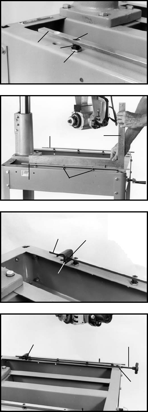
- ASSEMBLING 12
- TABLE CLAMPS AND 12
- TABLE CLAMP RODS 12
- AND BLADE GUARD 13
- ASSEMBLY 13
- TABLE BOARDS 13
- ASSEMBLING SAW BLADE 13
- ON/OFF SWITCH 15
- ADJUSTING OVERARM 15
- COLUMN ASSEMBLY 15
- ADJUSTING YOKE 15
- CLAMP HANDLE 15
- ADJUSTING CUTTINGHEAD 16
- BALL BEARINGS AGAINST 16
- TRACK RODS 16
- ADJUSTING TRACK RODS 16
- ADJUSTING BLADE SQUARE 17
- WITH TABLE TOP 17
- ADJUSTING TRACK ARM 18
- ADJUSTING SAW TRAVEL 19
- SQUARE WITH FENCE 19
- REMOVING “HEELING” 20
- IN SAW CUT 20
- CROSS-CUT STOP 20
- ADJUSTING BLADE GUARD 21
- AND ANTI-KICKBACK ROD 21
- ADJUSTING 21
- TRACK ARM STOP 21
- OPERATIONS 22
- MITER CUTTING 23
- COMPOUND MITER 23
- OUT-RIPPING 23
- IN-RIPPING 24
- PUSH STICK 25
- Two Year Limited Warranty 27
- • DELTA SERVICE CENTERS 28
- • DELTA) 28
Related products and manuals for Power saws Delta 33-891
 (1 pages)
(1 pages)
(1 pages)
© 2020, manymanuals.com. All rights reserved. | 0.414 s |
 Manymanuals.com
 Manymanuals.de
 Manymanuals.fr
 Manymanuals.it
 Manymanuals.pl
 Manymanuals.cz
 Manymanuals.es
 Manymanuals-pt.com
Comments to this Manuals