Delta 32-326 Instruction Manual
Browse online or download Instruction Manual for Power tools Delta 32-326. Delta 32-326 Instruction manual User Manual
- Page / 28
- Table of contents
- BOOKMARKS
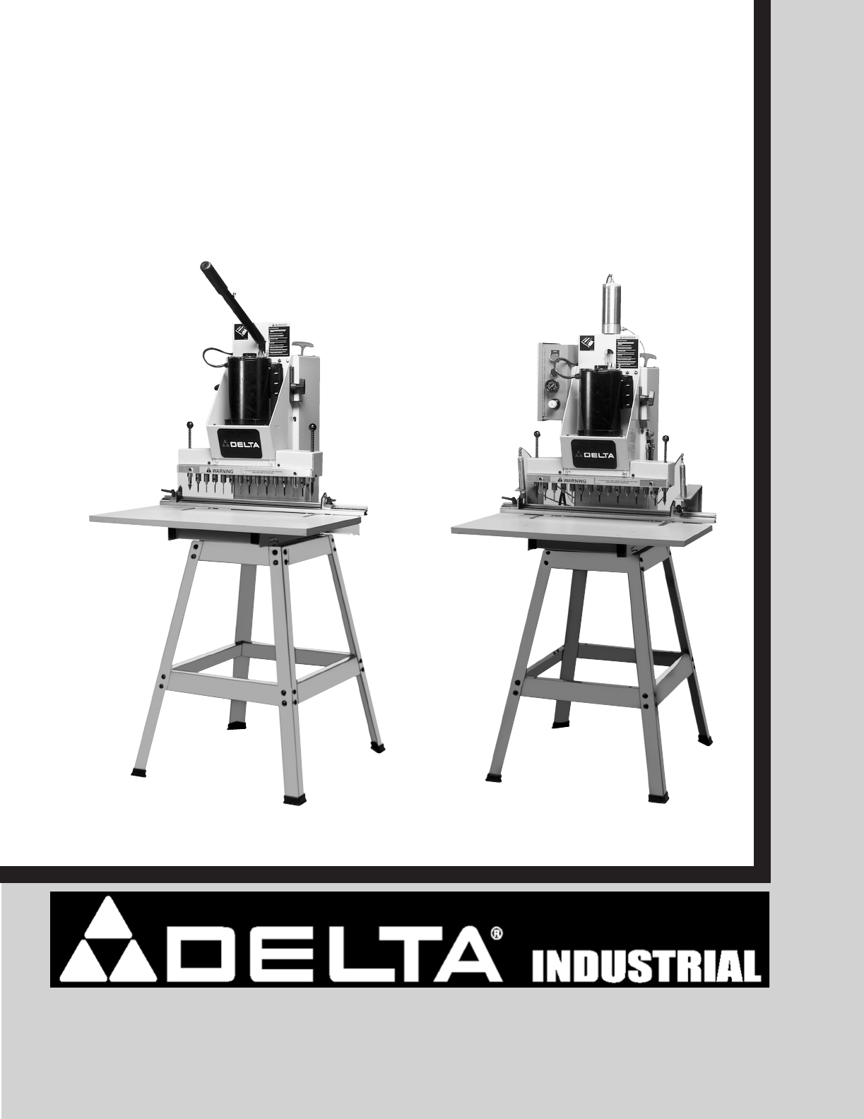
- 13-Spindle Pneumatic Line 1
- Boring Machine 1
- GENERAL SAFETY RULES 2
- ADDITIONAL SAFETY RULES 4
- FOR LINE BORING MACHINES 4
- POWER CONNECTIONS 5
- MOTOR SPECIFICATIONS 5
- GROUNDING INSTRUCTIONS 5
- FUNCTIONAL DESCRIPTION 6
- CARTON CONTENTS 7
- ASSEMBLY 9
- TABLE TO MACHINE 10
- FENCE TO MACHINE 11
- ALIGNING FENCE PARALLEL 11
- TO LINE BORING HEAD 11
- ADJUSTING TABLE 12
- PARALLEL TO FENCE 12
- AIR CYLINDER CLAMPS 14
- ASSEMBLING TABLE 14
- ASSEMBLING AIR FILTER 15
- ASSEMBLING BORING BITS 15
- TO SPINDLES 15
- ALIGNING BORING BITS 16
- ASSEMBLING CLEAR 16
- PLASTIC GUARD 16
- WRENCH STORAGE 16
- CONNECTING AIR TO 17
- ADJUSTING AIR 17
- PRESSURE 17
- STARTING AND 18
- STOPPING MACHINE 18
- LOWERING BORING HEAD 18
- LOCKING SWITCH 18
- IN THE “OFF” POSITION 18
- MOVING FENCE AND TABLE 20
- FENCE STOPS 21
- OPERATIONS 22
- CORRECT OPERATING 23
- TECHNIQUE 23
- ACCESSORIES 27
- • DELTA SERVICE CENTERS 28
- • DELTA) 28
Summary of Contents
INSTRUCTION MANUALPART NO. 449-01-651-0005 - 11-03-03Copyright © 2003 Delta MachineryTo learn more about DELTA MACHINERY visit our website at: www.del
10Fig. 8 Fig. 9Fig. 10Fig. 11TABLE TO MACHINE1. Clip the two table slides (A) Fig. 8, to the tablebracket (B) as shown.2. Clip the remaining two table
11Fig. 14Fig. 15FENCE TO MACHINE1. Place spacer (A) Fig. 14, over hole (B) in tablebracket with large countersunk end of spacer (A) in theup position.
12Fig. 18Fig. 196. Loosen the two screws (E) Fig. 15, that fasten fence(F) Fig. 19, to the machine and move fence (F) until frontsurface of fence cont
13Fig. 22 Fig. 23ABCAFig. 24Fig. 26ASSEMBLINGHEAD LOWERING ANDRAISING AIR CYLINDER(For 32-326 Pneumatic Line Boring MachineOnly)1. Remove retaining ri
14Fig. 28Fig. 27EFDBANLKGSHVRR4. Make certain air cylinder rod is retracted completelyinto cylinder (E) Fig. 27. Loosen locknut (K) Fig. 27, andunscre
15Fig. 33EHGFig. 34Fig. 35Fig. 36ASSEMBLING AIR FILTER(For 32-326 Pneumatic Line Boring MachineOnly)Thread air filter (A) Fig. 34, onto threaded stud
16Fig. 37ALIGNING BORING BITS(For 32-325 Line Boring Machine Only)1. Place a flat piece of wood (A) Fig. 37, on the tableand against the fence as show
17CONNECTING AIR TOMACHINE(For 32-326 Pneumatic Line Boring MachineOnly)A 1/4" female pipe thread (A) Fig. 43, is provided on theair filter for c
18Fig. 46Fig. 47Fig. 48Fig. 49STARTING ANDSTOPPING MACHINE(For 32-326 Pneumatic Line Boring MachineOnly)1. Plug the motor cord (A) Fig. 46, into outle
19Fig. 50Fig. 51Fig. 52MULTI-POSITIONLOWERING HANDLE(For 32-325 Line Boring Machine Only)For extra leverage when boring holes, the handle (B) Fig.50,
2Indicates an imminently hazardous situation which, if not avoided, will result in death or serious injury.Indicates a potentially hazardous situation
20Fig. 53Fig. 54Fig. 552. IMPORTANT: Before setting the limit switch depthsetting, make certain all assembly instructions forPNEUMATIC LINE BORING MAC
21Fig. 59Fig. 58FENCE STOPSTwo fence stops, one right (A) Fig. 58, and one left (B),are supplied with your boring machine. A scale (D) isprovided on t
22Fig. 63LINE BORING1. Figure 63 illustrates a typical line boring operationbeing performed on a workpiece. Note that the right endof the workpiece is
23Fig. 67CORRECT OPERATINGTECHNIQUE(For 32-326 Pneumatic Line Boring MachineOnly)The following is a typical example of a line boringoperation and how
24NOTES
25NOTES
26NOTES
27PARTS, SERVICE OR WARRANTY ASSISTANCEAll Delta Machines and accessories are manufactured to high quality standards and are serviced by a networkof P
The following are trademarks of PORTER-CABLE·DELTA (Las siguientes son marcas registradas de PORTER-CABLE S.A.): Auto-Set®,BAMMER®, B.O.S.S.®, Builder
3FAILURE TO FOLLOW THESE RULES MAY RESULT IN SERIOUS PERSONAL INJURY.1. FOR YOUR OWN SAFETY, READ THE INSTRUCTIONMANUAL BEFORE OPERATING THE MACHINE.L
4FAILURE TO FOLLOW THESE RULES MAY RESULT IN SERIOUS PERSONAL INJURY.ADDITIONAL SAFETY RULESFOR LINE BORING MACHINES SAVE THESE INSTRUCTIONS. Refer to
5A separate electrical circuit should be used for your machines. This circuit should not be less than #12 wire and shouldbe protected with a 20 Amp ti
6EXTENSION CORDSUse proper extension cords. Make sure your extension cord is in good condition and is a 3-wireextension cord which has a 3-prong groun
7CARTON CONTENTSINSTRUCTIONS LISTED AND SHOWN IN THIS MANUAL REFER TO BOTH THE 32-325 13-SPINDLE LINEBORING MACHINE AND 32-326 13-SPINDLE PNEUMATIC L
8Fig. 3Fig. 4Fig. 5For 32-326 13-SpindlePneumatic Line Boring MachineFor 32-325 13-Spindle Line Boring MachineFor 32-326 13-Spindle Pneumatic Line
9ASSEMBLYFOR YOUR OWN SAFETY, DO NOT CONNECT THE MACHINE TO THE POWER SOURCE UNTILTHE MACHINE IS COMPLETELY ASSEMBLED AND YOU READ AND UNDERSTAND THE
More documents for Power tools Delta 32-326

Related products and manuals for Power tools Delta 32-326
 (18 pages)
(29 pages)
(32 pages)
(17 pages)
(24 pages)
(16 pages)
(20 pages)
(23 pages)
(13 pages)
(28 pages)
(40 pages)
(21 pages)
(10 pages)
(16 pages)
(18 pages)
(29 pages)
(32 pages)
(17 pages)
(24 pages)
(16 pages)
(20 pages)
(23 pages)
(13 pages)
(28 pages)
(40 pages)
(21 pages)
(10 pages)
(16 pages)

 (76 pages)
(167 pages)
(17 pages)
(40 pages)
(76 pages)
(167 pages)
(17 pages)
(40 pages)
© 2020, manymanuals.com. All rights reserved. | 1.370 s |
 Manymanuals.com
 Manymanuals.de
 Manymanuals.fr
 Manymanuals.it
 Manymanuals.pl
 Manymanuals.cz
 Manymanuals.es
 Manymanuals-pt.com
Comments to this Manuals