Delta 36-650 Instruction Manual Page 22
- Page / 32
- Table of contents
- BOOKMARKS
- INSTRUCTION MANUAL 1
- GENERAL SAFETY RULES 2
- ADDITIONAL SAFETY RULES FOR 3
- TABLE SAWS 3
- POWER CONNECTIONS 4
- MOTOR SPECIFICATIONS 4
- GROUNDING INSTRUCTIONS 4
- OPERATING INSTRUCTIONS 5
- FENCE PARTS 6
- STAND PARTS 7
- HARDWARE 7
- ASSEMBLY 8
- BLADE TILTING AND 9
- RAISING HANDWHEEL 9
- INSTALLING SWITCH 10
- AND MOTOR CORD 10
- MOTOR TO MOTOR 11
- MOUNTING PLATE 11
- MOTOR AND MOTOR 11
- MOUNTING PLATE TO SAW 11
- DRIVE BELT 12
- MOTOR PULLEY 12
- PULLEY GUARD, AND 12
- CONNECTING MOTOR CORD 13
- TO SWITCH ASSEMBLY 13
- BLADE GUARD AND 14
- SPLITTER ASSEMBLY 14
- EXTENSION WINGS 16
- GUIDE RAILS AND 17
- SWITCH ASSEMBLY 17
- RIP FENCE TO GUIDE RAILS 18
- LOCKING SWITCH IN 19
- THE “OFF” POSITION 19
- STARTING AND 19
- STOPPING SAW 19
- RAISING AND LOWERING 20
- THE BLADE 20
- TILTING THE BLADE 20
- ADJUSTING 90 DEGREE AND 20
- 45 DEGREE POSITIVE STOPS 20
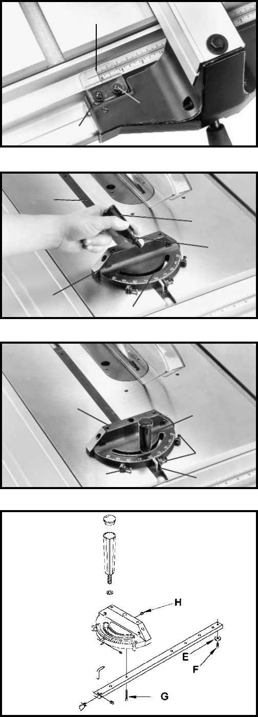
- MITER GAGE OPERATION 22
- AND ADJUSTMENT 22
- MAINTENANCE 23
- OPERATIONS 24
- USING ACCESSORY 25
- MOULDING CUTTERHEAD 25
- ALWAYS INSTALL BLADE 26
- GUARD AFTER OPERATION 26
- IS COMPETE 26
- DADO HEAD 27
- CONSTRUCTING A FEATHERBOARD 28
- PUSH STICK 29
- Two Year Limited Warranty 30
- • DELTA SERVICE CENTERS 32
- • DELTA) 32
Related products and manuals for Power tools Delta 36-650
 (16 pages)
(15 pages)
(16 pages)
(17 pages)
(27 pages)
(23 pages)
(28 pages)
(18 pages)
(29 pages)
(32 pages)
(17 pages)
(24 pages)
(16 pages)
(20 pages)
(23 pages)
(13 pages)
(28 pages)
(40 pages)
(16 pages)
(16 pages)
(15 pages)
(16 pages)
(17 pages)
(27 pages)
(23 pages)
(28 pages)
(18 pages)
(29 pages)
(32 pages)
(17 pages)
(24 pages)
(16 pages)
(20 pages)
(23 pages)
(13 pages)
(28 pages)
(40 pages)
© 2020, manymanuals.com. All rights reserved. | 0.614 s |
 Manymanuals.com
 Manymanuals.de
 Manymanuals.fr
 Manymanuals.it
 Manymanuals.pl
 Manymanuals.cz
 Manymanuals.es
 Manymanuals-pt.com
Comments to this Manuals