Delta 37-071 Instruction Manual
Browse online or download Instruction Manual for Power tools Delta 37-071. Delta 37-071 Instruction manual [de] [en] User Manual
- Page / 56
- Table of contents
- BOOKMARKS
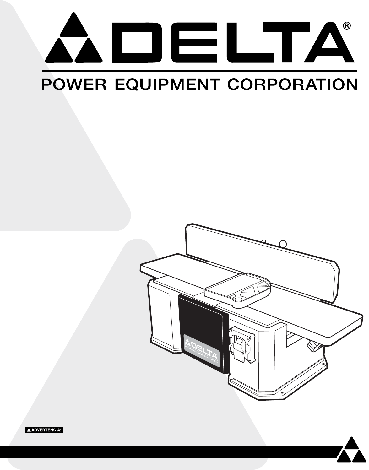
- 6 in. Bench Jointer 1
- TABLE OF CONTENTS 2
- IMPORTANT SAFETY INSTRUCTIONS 2
- GENERAL SAFETY RULES 3
- SAVE THESE INSTRUCTIONS 5
- POWER CONNECTIONS 6
- KEY FEATURES AND COMPONENTS 7
- FUNCTIONAL DESCRIPTION 7
- UNPACKING 9
- ASSEMBLY 10
- OPERATION 12
- MAINTENANCE 16
- OTHER RECOMMENDED MAINTENANCE 16
- ACCESSORIES 17
- WARRANTY 17
- REPLACEMENT PARTS 18
- SERVICE AND REPAIRS 18
- RÈGLES DE SÉCURITÉ GÉNÉRALES 21
- CONSERVEZ CES CONSIGNES 23
- RACCORDEMENTS ÉLECTRIQUES 24
- DESCRIPTION FONCTIONNELLE 25
- 8 9 10 11 12 13 26
- DÉBALLAGE 27
- FIGURE 5 FIGURE 6 28
- FIGURE 7 28
- FIGURE 8 28
- FIGURE 9 29
- FIGURE 10 29
- FONCTIONNEMENT 30
- ENTRETIEN 34
- AUTRE ENTRETIEN RECOMMANDÉ 34
- ACCESSOIRES 35
- GARANTIE 35
- PIÈCES DE RECHANGE 36
- SERVICE ET RÉPARATIONS 36
- REGLAS GENERALES DE SEGURIDAD 39
- GUARDE ESTAS INSTRUCCIONES 41
- CONEXIONES DE ALIMENTACIÓN 42
- DESCRIPCIÓN FUNCIONAL 43
- DESEMPAQUE 45
- ENSAMBLE 45
- FUNCIONAMIENTO 48
- MANTENIMIENTO 52
- ACCESORIOS 53
- GARANTÍA 53
- PIEZAS DE REPUESTO 54
- 5530 Airport Road 56
- Anderson, SC 29626 56
- (800) 223-7278 56
Summary of Contents
37-071Canteador de banco de 152 mm (6 pulg.)Dégauchisseuse d’établi de 152 mm (6 po)Instruction ManualManuel d’utilisationManual de instruccionesFran
10FENCE ANGLE LOCK ASSEMBLYALIGN CUTTERHEAD TO OUTFEED TABLEASSEMBLYFIGURE 5 FIGURE 6FIGURE 71. Feed the threaded end of the fence angle lock (A) thr
11ASSEMBLYFIGURE 9ALIGN CUTTERHEAD TO OUTFEED TABLE (continued)FIGURE 106. Loosen the four screws securing the clamp bar to the cutterhead. See Figur
12Make sure that the switch is in the "OFF" position before plugging cord into outlet. Do not touch the plug’s metal prongs when unplugging
13OPERATIONFEEDING STOCK1. Place the surface to be jointed face down on the infeed table and against the fence. Turn the jointer on and wait for the
14OPERATIONJOINTING BEVELED STOCK (continued)FIGURE 16INWARD 45° ANGLE:See Figure 16.1. Loosen the beveling lock (A) by rotating the handle countercl
15FIGURE 18TO CALIBRATE THE 45° INWARD AND OUTWARD STOPS:OPERATION1. Loosen the beveling lock by rotating the handle counterclockwise. 2. Refer to F
16MAINTENANCECHANGING CUTTERHEAD KNIVESDisconnect the machine from the power source before making any adjustments!Jointer knives are dangerously sharp
ACCESSORIESA complete line of accessories is available from your DELTA® Supplier, DELTA® Factory Service Centers, and DELTA® Factory Service Centers,
REPLACEMENT PARTSUse only identical replacement parts. For a parts list or to order parts, visit our website at www.DeltaMachinery.com/service. You ca
19
TABLE OF CONTENTSIMPORTANT SAFETY INSTRUCTIONS ...2SAFETY GUIDELINES - DEFINITIONS ...
20CONSIGNES DE SÉCURITÉ IMPORTANTESCONSIGNES DE SÉCURITÉ - DÉFINITIONSASSUREZ-VOUS D’AVOIR BIEN LU ET COMPRIS TOUTES LES MISES EN GARDE ET LES CONSIGN
21RÈGLES DE SÉCURITÉ GÉNÉRALESLE NON-RESPECT DE CES RÈGLES PEUT ENTRAÎNER DES BLESSURES PERSONNELLES GRAVES.•POUR VOTRE PROPRE SÉCURITÉ, ASSUREZ-VOUS
22RÈGLES DE SÉCURITÉ SPÉCIFIQUES SUPPLÉMENTAIRES1. N'UTILISEZ PAS CET APPAREIL AVANT qu’il soit entièrement assemblé et installé conformément au
23CONSERVEZ CES CONSIGNES.Consultez-les souvent et utilisez-les pour enseigner les autres.pièces plus petites vous pourriez toucher le porte-outil, pr
24FIG. A FIG. BBROCHES PORTEUSES DE COURANTLA BROCHE DE MISE À LA TERRE EST LA PLUS LONGUE DES TROISBOÎTE DE COURANT DE MISE À LA TERREBOÎTE DE COURA
25RALLONGESUtilisez des rallonges appropriées. Assurez-vous que la rallonge est en bon état et qu’il s’agit d’une rallonge à trois fils avec une fiche
26Comparez toutes les pièces à la liste ci-dessous et vérifiez que toutes les pièces sont présentes et en bon état. Signalez toute pièce manquante ou
27DÉBALLAGEASSEMBLAGE DU GUIDE1. Fixez le support de fixation du guide (A) à la base de la dégauchisseuse à l’aide de quatre vis à tête ronde M8 x 25
28ASSEMBLAGE DE LA BUTÉE ANGULAIRE DU GUIDEALIGNER LE PORTE-OUTIL À LA TABLE DE SORTIEMONTAGEFIGURE 5 FIGURE 6FIGURE 71. Insérer l'extrémité fil
29MONTAGEFIGURE 9ALIGNER LE PORTE-OUTIL À LA TABLE DE SORTIE (suite)FIGURE 105. Utiliser un morceau de bois pour maintenir le dispositif de protectio
SAFETY GUIDELINES - DEFINITIONSThis manual contains information that is important for you to know and understand. This information relates to protecti
30Assurez-vous que l’interrupteur est en position « OFF » (Arrêt) avant de brancher le cordon dans la prise. Ne touchez pas aux broches métalliques de
31FONCTIONNEMENTINTRODUCTION DU MATÉRIEL1. Placez la surface à jointoyer face vers le bas sur la table d'entrée et contre le guide. Allumez la d
32FONCTIONNEMENTJOINTOYER DU MATÉRIEL BISEAUTÉ (suite)FIGURE 16ANGLE DE 45° VERS L'INTÉRIEUR :Voir Figure 16.1. Desserrez le verrou de biseautag
33FIGURE 18POUR ÉTALONNER LES BUTÉES DE 45° ENTRANTES ET SORTANTES :FONCTIONNEMENT1. Desserrez le verrou de biseautage en tournant la poignée dans l
34ENTRETIENREMPLACEMENT DES LAMES DU PORTE-OUTILDébranchez l’appareil de la source d’alimentation avant de faire des ajustements!Les lames de la dégau
35AMÉRIQUE LATINE : La présente garantie ne s’applique pas aux produits vendus en Amérique latine. Pour les produits vendus en Amérique latine, veuill
36AIDE POUR LES PIÈCES, LE SERVICE OU LA GARANTIETous les appareils et accessoires DELTAMD sont fabriqués selon des normes de qualité élevées et sont
37
38INSTRUCCIONES IMPORTANTES DE SEGURIDADLEA Y COMPRENDA TODAS LAS ADVERTENCIAS E INSTRUCCIONES DE OPERACIÓN ANTES DE USAR ESTE EQUIPO. No cumplir con
39REGLAS GENERALES DE SEGURIDADNO SEGUIR ESTAS REGLAS DE SEGURIDAD PUEDE OCASIONAR LESIONES PERSONALES GRAVES.•POR SU PROPIA SEGURIDAD, LEA Y COMPREN
equipment such as adjusting keys, wrenches, scrap, stock, and cleaning rags are removed away from the machine before turning on.14. Keep safety guards
40REGLAS ESPECÍFICAS DE SEGURIDAD ADICIONALES1. NO OPERE ESTA MÁQUINA hasta que esté completamente ensamblada e instalada de acuerdo con las instrucc
41GUARDE ESTAS INSTRUCCIONES.Consúltelas con frecuencia y úselas para dar instrucción a otros.se coloque en la cabeza de corte provocando lesiones gra
42Se debe utilizar un circuito eléctrico por separado para sus máquinas. Este circuito no debe ser inferior a un cable calibre 12 y debe estar protegi
43ALARGADORES ELÉCTRICOSUtilice los alargadores eléctricos adecuados. Cerciórese de que los alargadores eléctricos estén en buenas condiciones y de qu
44Compare todas las partes con la siguiente lista y compruebe que todas las partes estén presentes y en buenas condiciones. Reporte cualquier parte qu
45DESEMPAQUEENSAMBLE DEL TOPE GUÍA1. Sujete la abrazadera de soporte del tope guía (A) al bastidor de la herramienta usando dos tornillos de cabeza d
46ENSAMBLE DEL SEGURO DEL ÁNGULO DEL TOPE GUÍAALINEACIÓN DE LA CABEZA DE CORTE CON LA MESA DE AVANCE DE SALIDAENSAMBLEFIGURA 5 FIGURA 6FIGURA 71. Pas
47ENSAMBLEFIGURA 9ALINEACIÓN DE LA CABEZA DE CORTE CON LA MESA DE AVANCE DE SALIDA (continuación)FIGURA 105. Use un pedazo de madera para mantener ab
48Asegúrese de que el interruptor esté en la posición de "OFF" (APAGADO) antes de conectar el cable al tomacorriente. No toque las puntas de
49FUNCIONAMIENTOALIMENTACIÓN DEL MATERIAL1. Coloque la superficie a cantear boca abajo en la mesa de avance de entrada y contra el tope guía. Enciend
SAVE THESE INSTRUCTIONS.Refer to them often and use them to instruct others.512. NEVER JOINT OR PLANE A WORKPIECE that is shorter than 10" (254mm
50FUNCIONAMIENTOCANTEAR MATERIAL BISELADO (continuación)FIGURA 164. Vuelva a ajustar el seguro de biselado. Use una escuadra para carpintero para com
51FIGURA 18PARA CALIBRAR LOS TOPES INTERIOR Y EXTERIOR DE 45°:FUNCIONAMIENTO1. Afloje el seguro de biselado girando la agarradera hacia la izquierda.
52MANTENIMIENTOCAMBIO DE CUCHILLAS DE LA CABEZA DE CORTEDesconecte la máquina de la fuente de poder antes de realizar cualquier ajuste.Las cuchillas d
53Garantía de producto nuevo limitada a cinco añosDELTA® reparará o sustituirá, a su cargo y opción, cualquier nueva máquina, repuesto o accesorio de
54PIEZAS DE REPUESTOUtilice solamente piezas de repuesto idénticas. Para obtener una lista de las piezas o para hacer un pedido de piezas, visite nues
55
5530 Airport Road Anderson, SC 29626 (800) 223-7278 www.DeltaMachinery.comCopyright © 2012 DELTA® Power Equipment Corporation DPEC002271 - 5-9-12
1. All grounded, cord-connected machines: In the event of a malfunction or breakdown, grounding provides a path of least resistance for electric curr
EXTENSION CORDS Use proper extension cords. Make sure your extension cord is in good condition and is a 3-wire extension cord which has a 3-prong gr
8Compare all parts to the list below and check that all parts are present and in good condition. Report any missing or damaged parts to your distribut
9UNPACKINGFENCE ASSEMBLY1. Attach the fence support bracket (A) to the tool frame using two M8 x 25mm socket head screws (B), each fitted with an 8mm
Related products and manuals for Power tools Delta 37-071
 (6 pages)
(10 pages)
(6 pages)
(10 pages)

 (88 pages)
(16 pages)
(20 pages)
(16 pages)
(14 pages)
(17 pages)
(14 pages)
(16 pages)
(12 pages)
(12 pages)
(21 pages)
(15 pages)
(14 pages)
(15 pages)
(88 pages)
(16 pages)
(20 pages)
(16 pages)
(14 pages)
(17 pages)
(14 pages)
(16 pages)
(12 pages)
(12 pages)
(21 pages)
(15 pages)
(14 pages)
(15 pages)
© 2020, manymanuals.com. All rights reserved. | 0.534 s |
 Manymanuals.com
 Manymanuals.de
 Manymanuals.fr
 Manymanuals.it
 Manymanuals.pl
 Manymanuals.cz
 Manymanuals.es
 Manymanuals-pt.com
Comments to this Manuals