Delta Delta JT360 Instruction Manual
Browse online or download Instruction Manual for Power tools Delta Delta JT360. Delta Delta JT360 Instruction manual User Manual
- Page / 76
- Table of contents
- TROUBLESHOOTING
- BOOKMARKS
- Instruction Manual 1
- Manuel d’utilisation 1
- Manual de instrucciones 1
- TABLE OF CONTENTS 2
- IMPORTANT SAFETY INSTRUCTIONS 2
- GENERAL SAFETY RULES 3
- SAVE THESE INSTRUCTIONS 4
- POWER CONNECTIONS 5
- MOTOR SPECIFICATIONS 5
- GROUNDING INSTRUCTIONS 5
- EXTENSION CORDS 6
- CARTON CONTENTS 7
- FUNCTIONAL DESCRIPTION 7
- JOINTER PARTS 8
- ASSEMBLY 9
- JOINTER TO STAND 10
- 11 - English 11
- DUST CHUTE COVER 12
- DUST COLLECTOR ADAPTER 12
- ADJUSTING BELT TENSION 13
- MOTOR PULLEY AND BELT GUARD 13
- MOTOR PULLEY 13
- BELT, ALIGNING PULLEYS, AND 13
- CUTTERHEAD GUARD 14
- OPERATION 15
- STEEL STRAIGHT EDGE 16
- OUT-FEED TABLE 16
- 17 - English 17
- ADJUSTING TABLE GIBS 18
- FENCE OPERATION 18
- 19 - English 19
- ADJUSTING FENCE GUARDS 20
- MACHINE USE 21
- JOINTING AN EDGE 22
- PLANING OR SURFACING 23
- BEVELING 23
- TAPER CUTS 23
- CUTTING A RABBET 23
- TROUBLESHOOTING 24
- MAINTENANCE 25
- ACCESSORIES 26
- WARRANTY 26
- CONSERVEZ CES INSTRUCTIONS! 27
- RÈGLES DE SÉCURITÉ GÉNÉRALES 28
- CONSERVER CES INSTRUCTIONS 29
- RACCORDEMENTS ÉLECTRIQUES 30
- SPÉCIFICATIONS DU MOTEUR 30
- CORDON DE RALLONGE 31
- DESCRIPTION FONCTIONNELLE 32
- CONTENUS DE BOITE 32
- DÉBALLAGE ET NETTOYAGE 33
- ASSEMBLAGE 34
- DÉGAUCHISSEUSE SUR LE SOCLE 35
- 36 - Français 36
- 37 - Français 37
- POULIE MOTRICE 38
- DE LA TENSION DE COURROIE 38
- POULIE MOTRICE ET GARDE 39
- PROTECTEUR DE COURROIE 39
- FONCTIONNEMENT 40
- 41 - Français 41
- DE LA FRAISE COUPANTE 42
- FONCTIONNEMENT DES GUIDES 43
- 44 - Français 44
- RÉGLAGE DES GARDES DU GUIDE 45
- UTILISATION DE LA MACHINE 46
- 3/4" (19 mm) MIN I MUM 47
- 10" (254 mm) MINIMUM 47
- 1/2" (12.7 mm) 47
- MIN I MUM 47
- RABOTAGE OU RESURFAÇAGE 48
- BISEAUTAGE 48
- DÉCOUPES CONIQUES 48
- COUPER UNE FEUILLURE 48
- DEPANNAGE 49
- ENTRETIEN 50
- ACCESSOIRIES 51
- GARANTIE 51
- PROPOSICIÓN DE CALIFORNIA 65 52
- NORMAS GENERALES DE SEGURIDAD 53
- GUARDE ESTAS INSTRUCCIONES 54
- 55 - Español 55
- CORDONES DE EXTENSIÓN 56
- DESCRIPCIÓN FUNCIONAL 57
- CONTENIDO DE CARTON 57
- ENSAMBLAJE 58
- MONTAJE DEL ESTANTE 59
- 60 - Español 60
- MONTAJE DE LA AGARRADERA DE 61
- MONTAJE DE LA TAPADERA DEL 61
- CONDUCTO DE POLVO 61
- 62 - Español 62
- MONTAJE DEL PROTECTOR DE 63
- POLEA DEL MOTOR Y DE LA 63
- OPERACIÓN 64
- ALIMENTACION 65
- BORDE RECTO DE ACERO 66
- FUNCIONAMIENTO DE LA GUIA 67
- DE LA GUIA 68
- 69 - Español 69
- UTILIZAR LA MAQUINA 70
- CANTEADOR UN BORDE 71
- ACEPILLADO O ALISADO 72
- BISELADO 72
- CORTES CONICOS 72
- CORTE DE ALEFRIZ 72
- LOCALIZACION DE FALLAS 73
- MESA DE 74
- AVANCE DE 74
- MESA DE ALIMENTACION 74
- ACCESORIOS 75
- GARANTIA 75
- PÓLIZA DE GARANTÍA 76
Summary of Contents
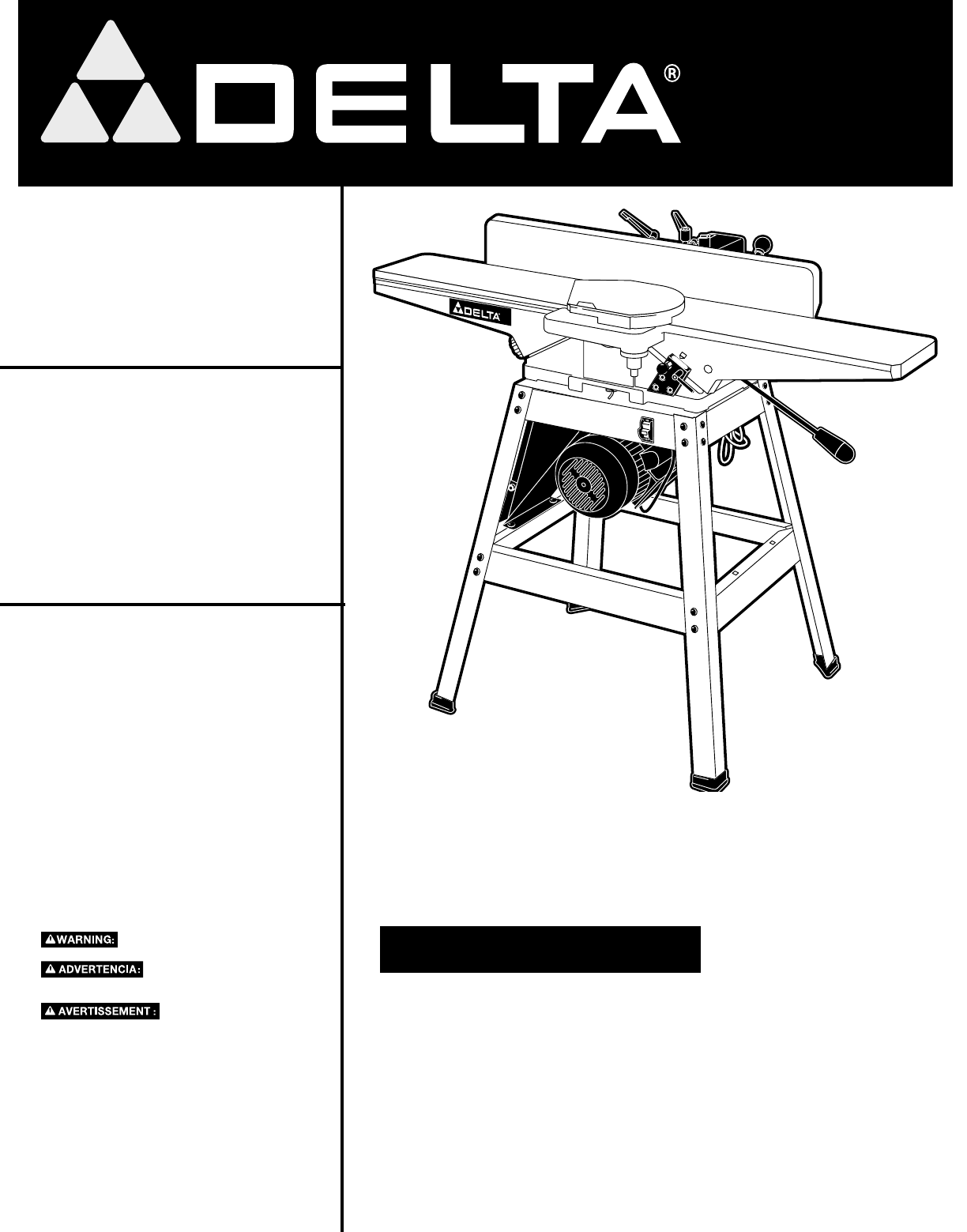
WWW.DELTAMACHINERY.COM(800) 223-7278 - US(800) 463-3582 - CANADACanteador de 152 mm (6 pulg)con base Dégauchisseuse de 152 mm (6 po)avec support6"
10 - EnglishJOINTER TO STANDJointer weight is approximately 175 lbs. Care must be taken when moving it. A minimum of two people will be required to li
11 - EnglishDD3. Using the supplied wrench (or a 14 mm socket wrench), fasten the jointer to the top of stand using the three M10.2 lockwashers and t
12 - EnglishINFEED TABLE ADJUSTMENT HANDLE1. Turn lock nut (C) Fig. 12, clock wise on infeed table ad just ment handle (B) as far as it will go.2. Th
13 - EnglishMOTOR PULLEYAssemble motor pulley (A) Fig. 16, to motor shaft, as shown. Make sure key (B) is inserted in the keyway of the motor pulley a
14 - EnglishFENCE1. Insert hexagon rod (A) Fig. 20, of fence assembly into bracket (B) on jointer as shown.2. Remove the M8x1.25x12mm long screw (D
15 - EnglishABCABOPERATIONOPERATIONAL CONTROLS AND ADJUSTMENTSSTARTING AND STOPPING JOINTER1. The on/off switch (A) Fig. 33 is located on the front
16 - English2. NOTE: When raising or lowering the infeed table a plunger located on other end of the index stop (C) Fig. 36, automatically stops the
17 - EnglishEDDFig. 414. CAREFULLY rotate the cutterhead by turning the belt by hand. The knives should just touch the straight edge.5. If the kni
18 - EnglishADJUSTING TABLE GIBS"Gibs" are provided to take up all play between the mating dovetail ways of the base and the infeed and outf
19 - EnglishADJUSTING FENCE POSITIVE STOPSThe fence on this jointer is equipped with positive stops that allow you to rapidly tilt the fence to the 90
2 - EnglishTABLE OF CONTENTSIMPORTANT SAFETY INSTRUCTIONSRead and understand all warnings and operating instructions before using any tool or equipmen
20 - EnglishB3. Using 8x10 mm open end wrench (A) Fig. 57, slightly loosen the four locking screws (B) in each knife slot by turning the screws (B)
21 - English9. The knives are adjusted correctly when the cutting edge of the knife extends out .060" (1.5 mm) from the cutterhead diameter.10. C
22 - EnglishDo not perform jointing operations on material shorter than 10" (254 mm), narrower than 3/4" (19 mm), or less that 1/2" (12
23 - EnglishPLANING OR SURFACINGPlaning or surfacing is identical to the jointing operation except for the position of the workpiece. For planing, the
24 - EnglishPLANING WARPED PIECESIf the wood to be planed is dished or warped, take light cuts until the surface is flat. Avoid forcing such material
25 - EnglishREMOVING DUST CHUTE COVERThe dust chute cover (A) Fig. 75, can be removed, for cleaning purposes, by removing the two wing screws (B). Mak
26 - EnglishA complete line of accessories is available from your Delta Supplier, Porter-Cable • Delta Factory Service Centers, and Delta Authorized
27 - FrançaisMESURES DE SÉCURITÉ - DÉFINITIONSCe guide contient des renseignements importants que vous deviez bien saisir. Cette information porte sur
28 - Français1. POUR SA SÉCURITÉ PERSONNELLE, LIRE LA NOTICE D’UTILISATION, AVANT DE METTRE LA MACHINE EN MARCHE, et pour aussi apprendre l’applicat
29 - FrançaisRÈGLES SPÉCIFIQUES ADDITIONNELLES DE SÛRETÉCONSERVER CES INSTRUCTIONS. Consultez les souvent et utilisez les pour enseigner à de nouveaux
3 - English1. FOR YOUR OWN SAFETY, READ THE INSTRUCTION MANUAL BEFORE OPERATING THE MACHINE. Learning the machine’s application, limitations, and spe
30 - FrançaisRACCORDEMENTS ÉLECTRIQUESUn circuit électrique séparé doit être utilisé pour les machines. Les fils de ce circuit doivent être au moins d
31 - FrançaisGROUNDED OUTLET BOXCURRENTCARRYINGPRONGSGROUNDING BLADEIS LONGEST OF THE 3 BLADESCORDON DE RALLONGEEmployez les cordes appropriées de pro
32 - Français13456789101112131415161718192223242202125262728293031323334353637AVANT-PROPOSLa dégauchisseuse de 152 mm (6 po) avec support est conçue p
33 - FrançaisCOMPOSANTES DE LA DÉGAUCHISSEUSEFig. 41. Moteur et interrupteur2. Dégauchisseuse3. Poulie motrice4. Courroie trapézoïdale 5. Deux entret
34 - FrançaisOUTILS REQUIS POUR L’ASSEMBLAGEASSEMBLY TIME ESTIMATE - 2-3 hours• Clé Allen de 6 mm • Clé Allen de 4 mm • Clé Allen de 3 mm • Clé Al
35 - FrançaisMOTEUR ET INTERRUPTEUR AU SOCLE1. Installez le moteur (B) Fig. 7, au bas de la goulotte de poussière. Alignez les quatre trous (F) Fig.
36 - FrançaisDD3. Utilisez la clé fournie (ou une clé à douille de 14 mm), fixez la dégauchisseuse sur le dessus du socle à l'aide de trois rond
37 - FrançaisPOIGNÉE DE RÉGLAGE DE LA TABLE D'ENTRÉE1. Sur la poignée de réglage de la table d'entrée (B), tournez le contre-écrou (C) Fig.
38 - FrançaisPOULIE MOTRICEInstallez la poulie (A) Fig. 16 à l'arbre du moteur tel qu'illustré. Assurez vous que la clé (B) est insérée dans
39 - FrançaisPOULIE MOTRICE ET GARDE PROTECTEUR DE COURROIEInstallez le garde poulie/courroie côté moteur (A) Fig. 19 à la base de la dégauchisseuse à
4 - English Failure to follow these rules may result in serious personal injury.SAVE THESE INSTRUCTIONS. Refer to them often and use them to instruct
40 - Français1. Retirez la vis de calage (A) Fig. 23, de la colonne (B) du garde protecteur de la tête de coupe (C).2. Installez le garde protecteur
41 - FrançaisRÉGLAGES DE LA TABLE D'ENTRÉE1. To raise or lower the infeed table, loosen table lockhandle (A) Fig. 35, move the table raising and
42 - Français3. Placez un bord droit sur la table de sortie, se prolongeant sur la tête de coupe tel que montré à la Fig. 39 et 42.4. TOURNEZ LENT
43 - FrançaisRÉGLAGE DES GLISSIÈRES DE TABLELes 'glissières' sont fournies pour retirer le jeu entre les queues d'aronde assorties de l
44 - FrançaisRÉGLAGE DES BUTÉES FIXES DE GUIDELe guide de cette dégauchisseuse est doté de butées fixes qui permettent d'incliner rapidement le g
45 - FrançaisB3. Utilisez une clé à fourche 8x10 mm (A) Fig. 57, et desserrez un peu les quatre vis de verrouillage (B) des fentes de couteau en tou
46 - Français9. Les couteaux sont réglés correctement lorsque le bord de coupe du couteau dépasse de 1,5 mm (0,060 po) du diamètre de la tête de cou
47 - Françaisne pas exécuter de jointage sur une pièce de travail de moins de 254 mm (10 po) de longueur, plus étroite que 19 mm (3/4 po) ou de moins
48 - FrançaisRABOTAGE OU RESURFAÇAGELe rabotage ou le resurfaçage sont des opérations semblables au jointage sauf pour ce qui a trait à la position de
49 - FrançaisRABOTAGE DE PIÈCES VOILÉESSi le bois à raboter est enfoncé ou voilé faire de légères coupes jusqu'à ce que la surface soit plane. É
5 - EnglishGROUNDED OUTLET BOXCURRENTCARRYINGPRONGSGROUNDING BLADEIS LONGEST OF THE 3 BLADESGROUNDED OUTLET BOXGROUNDING MEANSADAPTERPOWER CONNECTIONS
50 - FrançaisENTRETIENRETRAIT DU COUVERCLE DE GOULOTTE À POUSSIÈRELe couvercle de la goulotte à poussière (a) fig. 75 se retire aux fins de nettoyage
51 - FrançaisUne ligne complète des accessoires est fournie des centres commerciaux d'usine de par votre de Porter-Cable•Delta fournisseur, de Po
52 - EspañolLea y entienda todas advertencias y las instrucciones operadoras antes de utilizar cualquier instrumento o el equipo. Cuando se usa instru
53 - EspañolNORMAS GENERALES DE SEGURIDAD1. PARA SU PROPIA SEGURIDAD, LEA EL MANUAL DE INSTRUCCIONES ANTES DE UTILIZAR LA MÁQUINA. Al aprender la apl
54 - EspañolGUARDE ESTAS INSTRUCCIONES. Refiérase a ellas con frecuencia y utilícelas para adiestrar a otros.Si no se siguen estas normas, el resultad
55 - EspañolRepare o reemplace inmediatamente los cordones dañados o desgastados.2. Máquinas conectadas con cordón conectadas a tierra diseñadas par
56 - EspañolCAJA TOMACORRIENTE CONECTADA A TIERRATERMINALES QUE LLEVAN CORRIENTEEL TERMINAL DE CONEXIÓN A TIERRA ES EL MÁS LARGO DE LOS 3 TERMINALES3.
57 - EspañolDESCRIPCIÓN FUNCIONALPROLOGOEl Delta JT360 modelo es una canteador con la capacidad que corta diseñada de la anchura del 6 pulg. (152 mm),
58 - EspañolPIEZAS DE LA CANTEADORFig. 41. La llave del motor y del interruptor 2. Canteador3. Polea Del Motor4. V-Correa5. Dos apoyos del extremo s
59 - EspañolMONTAJE DEL ESTANTE1. Monte el soporte según lo demostrado en Fig. 5 usando las piezas demostradas en Fig. 4. Los apoyos, las piernas y l
6 - EnglishGROUNDED OUTLET BOXCURRENTCARRYINGPRONGSGROUNDING BLADEIS LONGEST OF THE 3 BLADESEXTENSION CORDSUse proper extension cords. Make sure your
60 - EspañolFig. 9ABCAFig. 9CDFig. 10COLOCAR LA CANTEADOR EN LA BASELa Canteador pesa aproximadamente 79 kg (175 lb). Al moverla se debe tener cuidado
61 - EspañolDFig. 11Fig. 11AMONTAJE DE LA AGARRADERA DE AJUSTE DE LA MESA DE ALIMENTACION1. Gire la tuerca de cierre (C) Fig. 12 en el sentido de las
62 - EspañolMONTAJE DEL ADAPTADOR DEL RECOLECTOR DE POLVOSi se piensa conectar la máquina a un sistema de recolección de polvo, la canteador viene equ
63 - EspañolMONTAJE DEL PROTECTOR DE POLEA DEL MOTOR Y DE LA CORREA Monte el protector de la polea del motor y de la correa poleas (A) Fig. 19, a la b
64 - EspañolMONTAJE DEL PROTECTOR DEL CABEZAL DE CORTE1. Quite el tornillo de fijación (A) Fig. 23 del poste (B) del protector del cabezal de corte (
65 - EspañolTOPES POSITIVOS DE LA MESA DE ALIMENTACIONSe proporcionan topes positivos para limitar la altura y la profundidad de la mesa de alimentaci
66 - EspañolCUCHILLAS FIJADAS DEMASIADO BAJOMATERIALMESA DE AVANCE DE SALIDAMESA DE ALIMENTACIONCABEZAL DE CORTECUCHILLAS FIJADAS DEMASIADO ALTOMATERI
67 - EspañolAJUSTE DE LAS CORREDERAS DE LA MESASe proporcionan "correderas" para quitar la holgura entre las guías de cola de milano de la b
68 - EspañolAJUSTANDO LOS TOPES POSITIVOS DE LA GUIALa guía en esta canteador viene equipada con topes positivos que le permiten inclinar la guía rápi
69 - EspañolAJUSTE DE LOS PROTECTORES DE LA GUIASe suministran dos guías, una de las cuales aparece en (A) Fig. 55, a cada lado del soporte de la guía
7 - English13456789101112131415161718192223242202125262728293031323334353637CARTON CONTENTS FOREWORDThe Delta JT360 6" (152mm) Jointer with Stand
70 - Español9. Las cuchillas quedan ajustadas correctamente cuando el borde cortante de cada cuchilla se extiende a .060 pulg. (1,53 mm) desde el diám
71 - EspañolDEFINICIONES DE LAS FUNCIONES DE CANTEADOR Y ACEPILLADOFunciones de canteador - Los cortes de canteador o el canteador de bordes constituy
72 - EspañolACEPILLADO O ALISADOEl acepillado o alisado es idéntico a la función de canteador, salvo por la posición del material. Para el acepillado,
73 - EspañolACEPILLADO DE MATERIALES ALABEADOSSi la madera a ser acepillada está curvada o alabeada, haga cortes ligeros hasta que la superficie esté
74 - EspañolAMOLADO DE CUCHILLASDesconecte la maquina de la fuente de potencia.Utilizando una piedra fina de carborundum, cúbrala parcialmente con pap
75 - EspañolUna línea completa de accesorios está disponible de su surtidor de Porter-Cable • Delta, centros de servicio de la fábrica de Porter-Cabl
The following are trademarks for one or more Porter-Cable and Delta products: Les marques suivantes sont des marques de commerce se rapportant à un
8 - EnglishJOINTER PARTSFig. 41. Motor and Switch2. Jointer3. Motor Pulley4. V-Belt5. Two Top End Braces for Stand (11-3/4")6. Two Top Side Bra
9 - EnglishASSEMBLYASSEMBLY TOOLS REQUIREDASSEMBLY TIME ESTIMATE - 2-3 hours* 6mm Allen Wrench* 4mm Allen Wrench* 3mm Allen Wrench* 2.5mm Allen Wrench
More documents for Power tools Delta Delta JT360

Related products and manuals for Power tools Delta Delta JT360
 (21 pages)
(16 pages)
(32 pages)
(16 pages)
(16 pages)
(15 pages)
(16 pages)
(17 pages)
(27 pages)
(23 pages)
(28 pages)
(18 pages)
(29 pages)
(32 pages)
(17 pages)
(24 pages)
(16 pages)
(20 pages)
(23 pages)
(21 pages)
(16 pages)
(32 pages)
(16 pages)
(16 pages)
(15 pages)
(16 pages)
(17 pages)
(27 pages)
(23 pages)
(28 pages)
(18 pages)
(29 pages)
(32 pages)
(17 pages)
(24 pages)
(16 pages)
(20 pages)
(23 pages)
© 2020, manymanuals.com. All rights reserved. | 6.659 s |
 Manymanuals.com
 Manymanuals.de
 Manymanuals.fr
 Manymanuals.it
 Manymanuals.pl
 Manymanuals.cz
 Manymanuals.es
 Manymanuals-pt.com
Comments to this Manuals