Delta DP400 Instruction Manual
Browse online or download Instruction Manual for Power tools Delta DP400. Delta DP400 Instruction manual User Manual
- Page / 23
- Table of contents
- TROUBLESHOOTING
- BOOKMARKS
- INSTRUCTION MANUAL 1
- TABLE OF CONTENTS 2
- IMPORTANT SAFETY INSTRUCTIONS 2
- CALIFORNIA PROPOSITION 65 3
- GENERAL SAFETY RULES 4
- SAVE THESE INSTRUCTIONS 5
- POWER CONNECTIONS 6
- MOTOR SPECIFICATIONS 6
- GROUNDING INSTRUCTIONS 6
- EXTENSION CORDS 7
- FUNCTIONAL DESCRIPTION 8
- CARTON CONTENTS 9
- 21" MINIMUM 10
- SPINDLE SPEEDS 17
- CHANGING SPEEDS AND 17
- ADJUSTING BELT TENSION 17
- DRILLING HOLES TO DEPTH 18
- ADJUSTING SPINDLE 18
- RETURN SPRING 18
- REMOVING DRILL BITS 19
- CORRECT DRILLING SPEEDS 19
- MACHINE USE 19
- INSTALLING AND 19
- BORING IN WOOD 20
- DRILLING METAL 20
- REMOVING SPINDLE ADAPTER 20
- TROUBLESHOOTING 21
- MAINTENANCE 22
- ACCESSORIES 22
- WARRANTY 22
- • DELTA SERVICE CENTERS 23
- • DELTA) 23
Summary of Contents
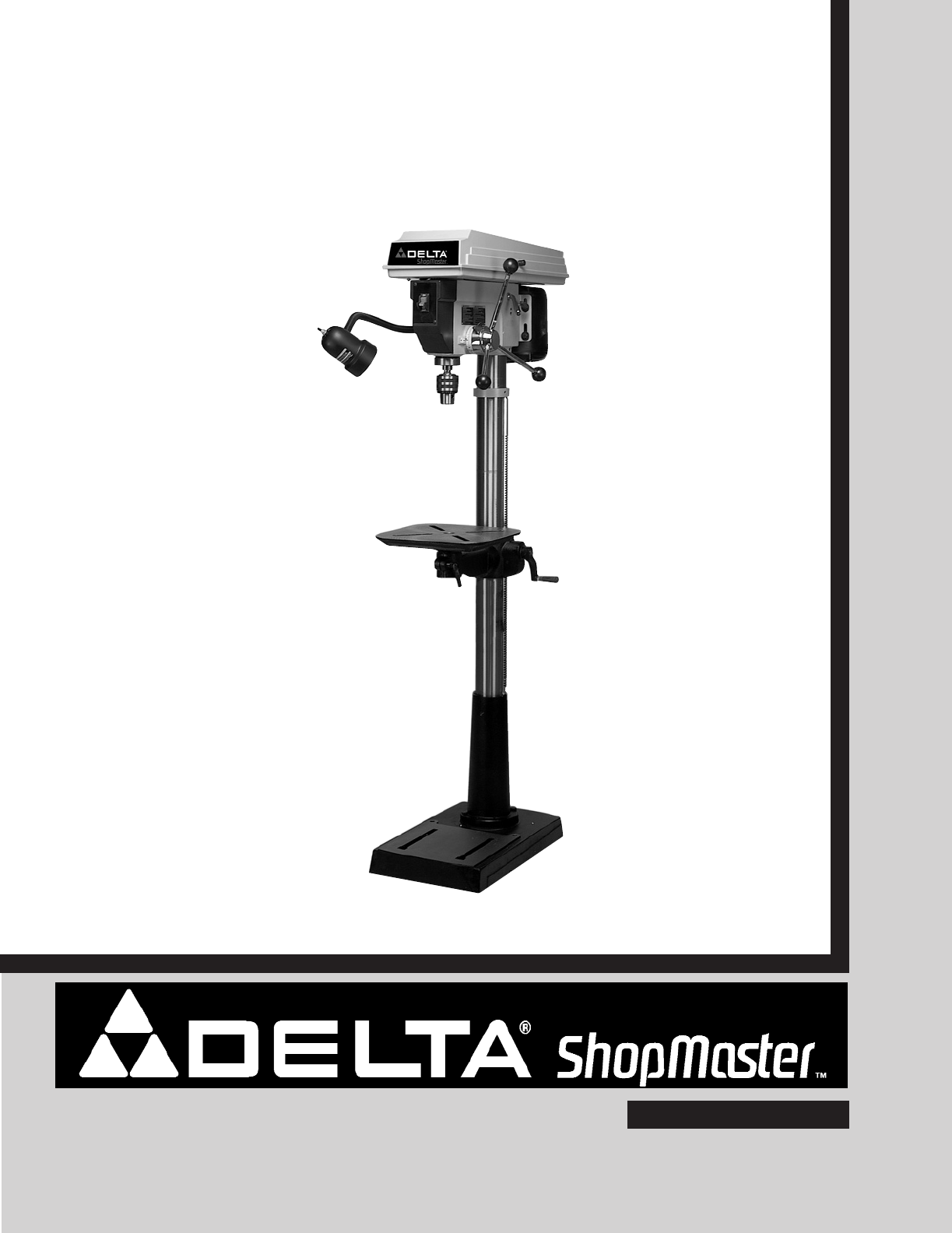
INSTRUCTION MANUAL16½" Floor Model Drill Press(Model DP400)PART NO. A10352 - 03-28-05Copyright © 2005 Delta MachineryESPAÑOL: PÁGINA 23To learn m
10ASSEMBLYFOR YOUR OWN SAFETY, DO NOT CONNECT THE MACHINE TO THE POWER SOURCE UNTIL THEMACHINE IS COMPLETELY ASSEMBLED AND YOU READ AND UNDERSTAND THE
THE PLYWOOD BASE MUST BESECURED TO THE FLOOR OR SUPPORTINGSURFACE IF THERE IS ANY TENDENCY OF THEDRILL PRESS TO VIBRATE, SLIDE OR WALKDURING NORMAL OP
12Fig. 99. Insert table (H) Fig. 9, into hole in table bracket asshown.Fig. 1010. Thread table locking lever (J) Fig. 10, into hole infront of table b
13Fig. 1414. IMPORTANT: Make certain the spindle taper (O) Fig.14, and tapered hole in chuck (P) are clean and free ofany grease, lacquer or rust prev
1418. Align the two holes in the lamp bracket (A) Fig. 17,with the two holes (B) on the side of the drill press head.Fig. 1720. Align the two holes in
STARTING AND STOPPINGDRILL PRESSThe switch (A) Fig. 20, is located on the front of the drillpress head. To turn the drill press “ON” move the switchup
16Fig. 24CE3. The table can be tilted right or left by pulling out andremoving table alignment pin (C) Fig. 24. NOTE: If pin (C)is difficult to remove
17SPINDLE SPEEDSTwelve spindle speeds are available on the drill press. Fig. 27, illustrates which steps of the pulleys the belts must beplaced to obt
18DRILLING HOLES TO DEPTHWhere a number of holes are to be drilled to exactly thesame depth, a depth stop is provided and is used asfollows:DISCONNECT
19Fig. 32Your drill press is to be used with drill bits with a shank of5/8" or less in diameter. The following will give theinexperienced operato
2TABLE OF CONTENTSRead and understand all warnings and operating instructions before using any tool or equipment. Whenusing tools or equipment, basic
20BORING IN WOODTwist drills, although intended for metal drilling, may also be used for boring holes in wood. However, machine spur bitsare generally
21TROUBLESHOOTINGFor assistance with your machine, visit our website at www.deltamachinery.com for a list of service centers or callthe DELTA Machiner
22MAINTENANCEPARTS, SERVICE OR WARRANTY ASSISTANCEAll Delta Machines and accessories are manufactured to high quality standards and are serviced by a
The following are trademarks of PORTER-CABLE •DELTA (Las siguientes son marcas registradas de PORTER-CABLE • DELTA S.A.) (Les marquessuivantes sont de
3Indicates an imminently hazardous situation which, if not avoided, will result in death or serious injury.Indicates a potentially hazardous situation
4GENERAL SAFETY RULESREAD AND UNDERSTAND ALL WARNINGS AND OPERATING INSTRUCTIONS BEFOREUSING THIS EQUIPMENT. Failure to follow all instructions listed
5ADDITIONAL SPECIFIC SAFETY RULESFAILURE TO FOLLOW THESE RULES MAY RESULT IN SERIOUS INJURY.1. DO NOT OPERATE THIS MACHINE until it iscompletely assem
6A separate electrical circuit should be used for your machines. This circuit should not be less than #12 wire and shouldbe protected with a 20 Amp ti
7EXTENSION CORDSUse proper extension cords. Make sure your extension cord is in good condition and is a 3-wireextension cord which has a 3-prong groun
8FOREWORDDelta ShopMaster DP400 is a 16½" drill press with a 120/240 V, 3/4 H.P. induction motor, a flexible work lamp and atilting table with c-
9CARTON CONTENTS12345678910111213141516171820212219Fig. 21. Drill Press Head2. Table3. Table Bracket and Column4. Light5. Base6. Chuck7. Handle (3)8.
Related products and manuals for Power tools Delta DP400
 (13 pages)
(28 pages)
(40 pages)
(21 pages)
(10 pages)
(16 pages)
(13 pages)
(28 pages)
(40 pages)
(21 pages)
(10 pages)
(16 pages)

 (76 pages)
(167 pages)
(17 pages)
(40 pages)
(16 pages)
(8 pages)
(76 pages)
(167 pages)
(17 pages)
(40 pages)
(16 pages)
(8 pages)
 (44 pages)
(64 pages)
(64 pages)
(20 pages)
(48 pages)
(4 pages)
(16 pages)
(44 pages)
(64 pages)
(64 pages)
(20 pages)
(48 pages)
(4 pages)
(16 pages)
© 2020, manymanuals.com. All rights reserved. | 0.940 s |
 Manymanuals.com
 Manymanuals.de
 Manymanuals.fr
 Manymanuals.it
 Manymanuals.pl
 Manymanuals.cz
 Manymanuals.es
 Manymanuals-pt.com
Comments to this Manuals