Delta ts200ls Instruction Manual
Browse online or download Instruction Manual for Power tools Delta ts200ls. Delta ts200ls Instruction manual User Manual
- Page / 52
- Table of contents
- TROUBLESHOOTING
- BOOKMARKS
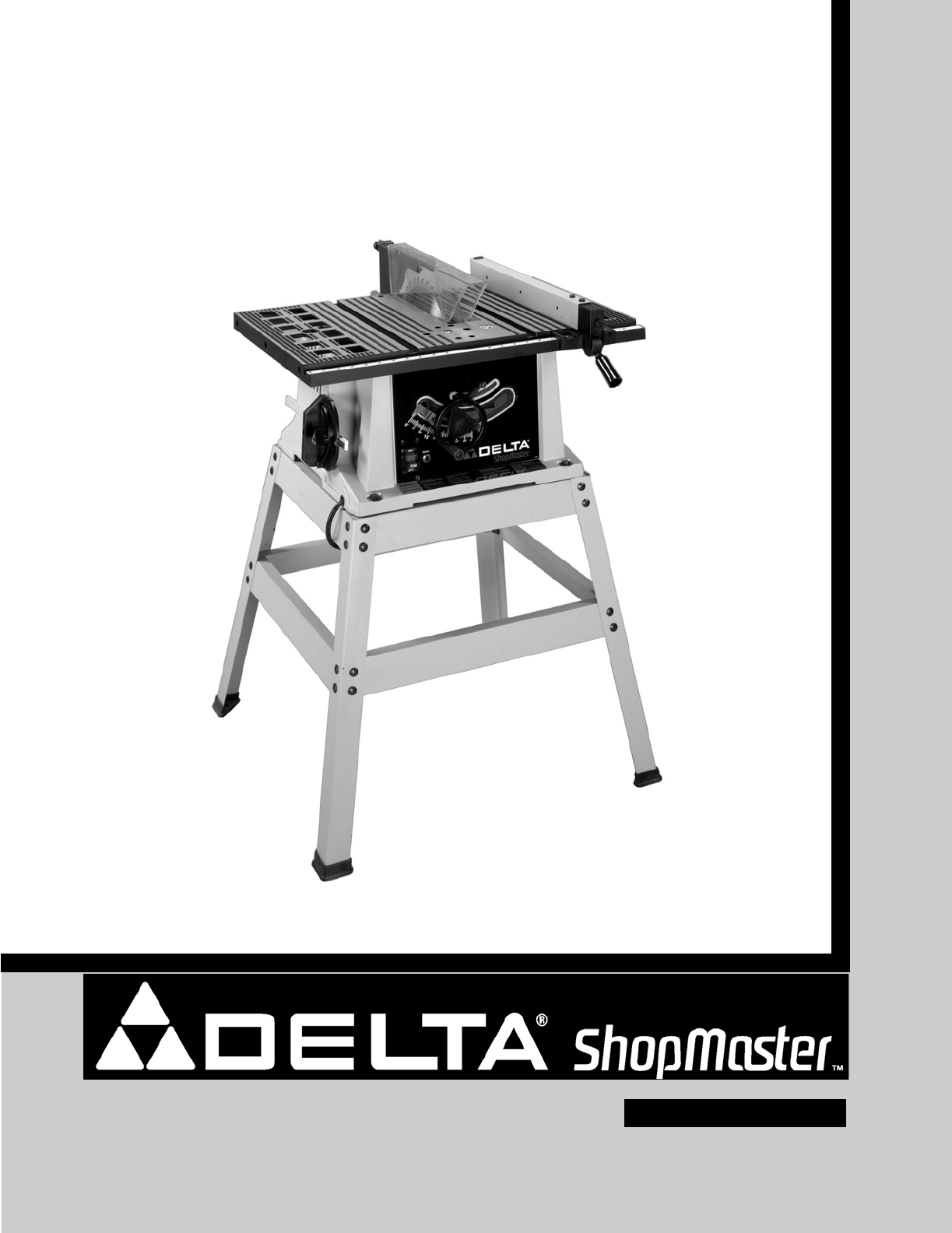
- 10" Motorized 1
- Bench Saw 1
- TABLE OF CONTENTS 2
- IMPORTANT SAFETY INSTRUCTIONS 2
- CALIFORNIA PROPOSITION 65 3
- GENERAL SAFETY RULES 4
- SAVE THESE INSTRUCTIONS 5
- Refer to them often 5
- POWER CONNECTIONS 6
- MOTOR SPECIFICATIONS 6
- GROUNDING INSTRUCTIONS 6
- FUNCTIONAL DESCRIPTION 7
- CARTON CONTENTS 7
- STAND FOR MODEL 8
- TS200LS ONLY (Fig. 4) 8
- Fig. 2 Parts 8
- Fig. 3 Hardware 8
- ASSEMBLY 9
- SAW TO STAND - TS200LS ONLY 10
- MITER GAUGE 13
- ATTACHING MITER GAUGE HOLDER 13
- ASSEMBLING RIP FENCE 14
- OPERATION 15
- BLADE TILT ADJUSTMENT 16
- AND ADJUSTMENTS 17
- TABLE INSERT ADJUSTMENT 17
- RIP FENCE OPERATION 17
- MITER GAUGE OPERATION 18
- MACHINE USE 19
- ACCESSORY DADO CUTTERHEAD 21
- USING AUXILIARY WOOD FACING 21
- ON RIP FENCE 21
- PUSH STICK 23
- TROUBLESHOOTING 24
- MAINTENANCE 25
- ACCESSORIES 25
- WARRANTY 25
- Sierra Motorizada de Banco 27
- PROPOSICIÓN DE CALIFORNIA 65 28
- NORMAS GENERALES DE SEGURIDAD 29
- PARA SIERRA DE MESA 31
- ESPECIFICACIONES DEL MOTOR 32
- CONTENIDO DE CARTON 33
- SOPORTE PARA EL MODELO 34
- TS200LS (Fig. 4) 34
- ENSAMBLAJE 35
- SIERRA QUE ENSAMBLA PARA 36
- ESTAR PARADO - TS200LS 36
- ESCUADRA DE INGLETES 38
- OPERACIÓN 40
- UTILIZAR LA MAQUINA 44
- REALIZACIÓN DE CORTES AL HILO 45
- ANCHURA DE LA MESA 46
- DE LA SIERRA + 2" 46
- PARA CORTAR AL HILO 47
- FRESA DE RANURAR ACCESORIA 47
- GUIA LOCALIZACION DE FALLAS 49
- VARA DE EMPUJE 50
- Garantía Limitada de Dos Años 51
- • DELTA SERVICE CENTERS 52
- • DELTA) 52
Summary of Contents
10" MotorizedBench Saw(Model TS200, Model TS200LS)Model TS200LSShownINSTRUCTION MANUALPART NO. A05738 - 05-19-05Copyright © 2005 Delta MachineryT
10ASSEMBLING STAND FOR MODEL TS200LS1. Assemble the stand as shown in Fig. 4C, using 16M8x1.25x20mm carriage head bolts, 3/8" flat washersand M8x
11Fig. 5Fig. 6Fig. 7ATTACHING BLADE HEIGHT ADJUSTING HANDWHEEL1. Insert an M6x1x55mm pan head screw (D) Fig. 5 through the handle (E). Attach the hand
12Fig. 14LBHCFig. 10Fig. 13Fig. 12Fig. 113. Locate the 1/4-20x2½" hex head screw (G) Fig. 10. Place the 1/4" internal tooth lockwasher (O) M
13Fig. 18Fig. 15Fig. 17Fig. 16NOTE: Before tightening the wing nut (M) Fig. 15,make certain a gap of at least 1/8" is between thebottom edge of t
14Fig. 24Fig. 26Fig. 25ASSEMBLING RIP FENCE1. Thread the M8x1.25 hex nut (A) Fig. 24, approximately halfway on the stud of the handle (B).2. Thread th
15BLADE HEIGHT ADJUSTMENTTo adjust the height of the saw blade, turn thehandwheel (A) Fig. 29. Turning the handwheel clockwiselowers the blade and tur
16Fig. 30ABBLADE TILT ADJUSTMENTTo tilt the saw blade, loosen the lock handle (A)Fig. 30 and move the handwheel (B) until the blade is atthe desired a
17RIP FENCE OPERATIONAND ADJUSTMENTS1. To move the rip fence (A) Fig. 33 along the table, liftup the fence locking lever (B), slide the fence to thede
18MITER GAUGE OPERATIONAND ADJUSTMENTSFor cross-cutting (blade set 90 degrees to the table), themiter gauge can be used in either table slot. For beve
19Fig. 381. NOTE: One 7/8" wrench is supplied with the saw forchanging the saw blade.2. Remove table insert (A) Fig. 38, and raise saw blade(F) t
2TABLE OF CONTENTSRead and understand all warnings and operating instructions before using any tool or equipment. Whenusing tools or equipment, basic
20Fig. 39AACBFig. 39BBor more to one side or the other depending on whichmiter gage slot is being used. This auxiliary wood-facing(B) can be fastenedt
21Fig. 42Fig. 43THE MAXIMUM WIDTH DADO CUT FORTHIS SAW IS 1/2 INCH.THE BLADE GUARD AND SPLITTERASSEMBLY CANNOT BE USED WHEN DADOING. ITMUST BE REMOVED
22Fig. 47Fig. 48Fig. 45 Fig. 46Fig. 44A1. Dadoing is cutting a rabbet or wide groove into thework. Most dado head sets are made up of two outsidesaws
23PUSH STICKMAKE FROM 1/2" OR 3/4"WOOD OR THICKNESSLESS THAN WIDTH OFMATERIAL TO BE CUTCUT OFF HERE TOPUSH 1/4" WOODCUT OFF HERE TOPUSH
24Fig. 49Fig. 50Kerf should beabout 1/4" apart.TROUBLESHOOTINGFor assistance with your machine, visit our website at www.deltamachinery.com for a
25MAINTENANCEPARTS, SERVICE OR WARRANTY ASSISTANCEAll Delta Machines and accessories are manufactured to high quality standards and are serviced by a
26NOTES
2727272727Sierra Motorizada de Bancode 10 pulg.(Modelo TS200, Modelo TS200LS con el soporte)PART NO. A05738 - 07-29-04Copyright © 2004 Delta Machinery
2828282828Lea y entienda todas advertencias y las instrucciones operadoras antes de utilizar cualquier instrumento o el equipo.Cuando se usa instrumen
29NORMAS GENERALES DE SEGURIDADLea todas las instrucciones. Si no se siguen todas las instrucciones que aparecen acontinuación, el resultado podría se
3Indicates an imminently hazardous situation which, if not avoided, will result in death or serious injury.Indicates a potentially hazardous situation
30NORMAS GENERALES DE SEGURIDADalimentación. En caso de un apagón, mueva elinterruptor a la posición de apagado. Un arranqueaccidental podría causar l
31REGLAS DE SEGURIDAD ADICIONALESPARA SIERRA DE MESA1. NO UTILICE ESTA MÁQUINA hasta que estécompletamente montada e instalada de acuerdo con lasinstr
3232Debe utilizarse un circuito eléctrico independiente para las máquinas. Este circuito debe tener alambre de no menosdel No. 12 y debe estar protegi
33INSTRUCCIONES DE FUNCIONAMIENTOLa ShopMaster modelo TS200LS de Delta es una sierra de mesa de 10" diseñada para brindar un rendimiento de altac
34Fig. 418971036245SOPORTE PARA EL MODELOTS200LS (Fig. 4)1. Pata (4)2. Arandela plana de 3/8" para montar la sierra en la basede soporte & pa
35ENSAMBLAJEDESEMPAQUETADO Y LIMPIEZADesempaque cuidadosamente la máquina y todas las piezas sueltas que están en el contenedor o contenedores detrans
36363636Fig. 5DEA1. Inserte el tornillo de M6x1x55 screw (D) Fig. 5, através de la agarradera (E) y ensamble la agarradera (E)al volante de mano (A) m
372. Ensamble el volante de mano (A) Fig. 6 al eje (B), asegurando que el plano en el lado interior del volante de manose alinee con el plano del eje.
3838383838387. Afiance el hendidor (L) Fig. 14 al soporte de apoyodel hendidor utilizando una arandela plana, unaarandela de cierre de dientes externo
391. Ensamble fig. 19 del (E) del clip de resorte, el (A) del sostenedor de la galga de los ingletes según lo mostradousando un tornillo de la pista d
4GENERAL SAFETY RULESREAD AND UNDERSTAND ALL WARNINGS AND OPERATING INSTRUCTIONS BEFOREUSING THIS EQUIPMENT. Failure to follow all instructions listed
4040404040Fig. 24Fig. 26Fig. 25BADCDBAENSAMBLADO DE LA GUIA DECORTE A LO LARGO1. Enrosque la M8x1.25 tuerca de cierre (A) Fig. 24aproximadamente a la
41Fig. 28BCFIJANDO EL INTERRUPTOR EN LAPOSICION DE APAGADOSugerimos que cuando la sierra no se encuentre en usoque el interruptor quede fijado en la p
4242424242424242DESCONCTE LA MAQUINA DE LA FUENTE DE ALIMENTACION.AJUSTANDO LOS TOPES POSITIVOS DE 90 Y 45 GRADOSSu sierra está equipada con topes pos
433. La hoja de la sierra está colocada de forma paralela a la ranura de la escuadra de ingletes en la fábrica, y la guía debeestar paralela a la ranu
4444444444444444Fig. 38FCEDBA1. Eleve la hoja a su elevación máxima y ajuste la hoja paraque quede a 90 grados de la mesa.2. Escoja un diente en la ho
45Comience el corte lentamente y sujete firmemente la piezade trabajo contra el calibre de ingletes y la mesa. UNA DE LAS REGLAS PARAUTILIZAR UNA SIER
46464646464646Fig. 41Fig. 431. Arranque el motor y haga avanzar la pieza de trabajosujetándola hacia abajo y contra el tope-guía. No se sitúenunca en
47Fig. 43AAFig. 44ABUTILIZACIÓN DE UN REFRENTADO DEMADERA AUXILIAR EN EL TOPE-GUÍAPARA CORTAR AL HILOEn algunas operaciones especiales se necesitan re
48CONSTRUCCIÓN DE UNA TABLA DE CANTO BISELADOEn la Fig. 49 se ilustran las dimensiones para hacer una tabla de canto biselado típica. El material con
49Fig. 49La separación de corte debe seraproximadamente 1/4".Fig. 50La información adicional sobre la operaciónsegura y apropiada de las sierras
5ADDITIONAL SPECIFIC SAFETY RULESSAVE THESE INSTRUCTIONS. Refer to them often and use them to instruct others. FAILURE TO FOLLOW THESE RULES MAY RESUL
50CORTE AQUI PARA EMPUJAR†MADERA DE 1/4" (6.4 mm)CORTE AQUI PARA EMPUJAR†MADERA DE 1/2" (12.7 mm)MUESCA PARA AYUDARA PREVENIR QUE LAMANO SE
51MANTENIMIENTOMANTENGA LAS HERRAMIENTAS LIMPIASPeriódicamente sople todos los conductos de ventilación con aire seco a presión. Todas las partes de p
The following are trademarks of PORTER-CABLE •DELTA (Las siguientes son marcas registradas de PORTER-CABLE • DELTA S.A.) (Les marquessuivantes sont de
66A separate electrical circuit should be used for your machines. This circuit should not be less than #12 wire and shouldbe protected with a 20 Amp t
7FUNCTIONAL DESCRIPTIONNOTICE: THE PHOTO ON THE MANUAL COVER ILLUSTRATES THECURRENT PRODUCTION MODEL. ALL OTHER ILLUSTRATIONS CONTAINEDIN THE MANUAL
818971036245Fig. 41. Leg (4)2. 3/8” Flat Washer for Mounting Saw toStand & for Assembling Stand (24)3. Foot (4)4. M8x1.25 Hex Nut for Mounting S
9UNPACKING AND CLEANINGCarefully unpack the machine and all loose items from the shipping container(s). Remove the protective coating fromall unpainte
More documents for Power tools Delta ts200ls

Related products and manuals for Power tools Delta ts200ls

 (48 pages)
(28 pages)
(48 pages)
(21 pages)
(15 pages)
(48 pages)
(28 pages)
(48 pages)
(21 pages)
(15 pages)
 (84 pages)
(16 pages)
(18 pages)
(22 pages)
(16 pages)
(24 pages)
(18 pages)
(14 pages)
(17 pages)
(24 pages)
(21 pages)
(23 pages)
(21 pages)
(16 pages)
(84 pages)
(16 pages)
(18 pages)
(22 pages)
(16 pages)
(24 pages)
(18 pages)
(14 pages)
(17 pages)
(24 pages)
(21 pages)
(23 pages)
(21 pages)
(16 pages)
© 2020, manymanuals.com. All rights reserved. | 1.359 s |
 Manymanuals.com
 Manymanuals.de
 Manymanuals.fr
 Manymanuals.it
 Manymanuals.pl
 Manymanuals.cz
 Manymanuals.es
 Manymanuals-pt.com
Comments to this Manuals