B. ADJUSTING THE ROTATIONAL LIMIT STOP
1. Read complete instructions and familiarize yourself with the illustrations before
beginning. Plumber installation is recommended.
2. WARNING! SHUT OFF WATER SUPPLIES BEFORE DISASSEMBLING THE TUB
SHOWER VALVE.
3. Remove handle. For knob handle, remove handle button and handle screw. for
lever handle, remove set screw on side of handle.
4. Pull outside sleeve (C) off. Then, if necessary, slide the sleeve O-Ring (D) toward
you until it stops at the raised brass section (E) on the tub/shower body. Do
not pull the sleeve O-Ring over the raised brass section. NOTE: when the sleeve
is re-installed, it will slide on this O-Ring.
5. BE SURE WATER SUPPLIES ARE SHUT OFF!
6. Unscrew the brass bonnet (F).
7. CAUTION! Note the position of the hot side of the cartridge labeled “HOT
SIDE”. Re-install the handle on brass stem (H) and rotate clockwise while lifting
the cartridge out of the two notches on the sides of the body. If the cartridge
cannot be removed by hand after rotating and lifting, then remove handle and
gently grasp the valve stem with pliers and remove the cartridge.
8. CAUTION! Do not twist the Cap and Lower Housing of the New Cartridge to
take it apart. If they are separated for any reason, be sure they are locked back
together by twisting them together until they snap back together. WARNING!
Never take the Lower Housing Apart.
9. Install the cartridge with the "HOT SIDE" lettering on the cap (B) on the hot
water inlet side (see Step 7). Insert cartridge until it is seated properly and tabs
on white cap are fully engaged in notches on the brass body (I).
10. Re-assemble the brass bonnet (F). Hand tighten securely.
11. Slide on the outside sleeve (C) (see Step 4).
12. IMPORTANT: Check for proper installation of the RLS (A) on the new cartridge
by following Step B.
13. Re-install the handle.
14. FLUSH YOUR SYSTEM. Turn handle to full on “hot and cold mix” position. Turn
on water supplies. Check for leaks and let supply lines flush for one minute
without moving handle. If you have a showerhead, divert water to it and flush
for 30 seconds. This will remove any debris from the supply lines that can
damage internal parts of the faucet and create leaks. BE SAFE! After you
have finished the repair, turn on tub/shower valve to make sure COLD WATER
FLOWS FIRST. If not, see Step 7.
IMPORTANT: The Rotational Limit Stop is used to limit the amount of hot water
available such that, if set properly, the user will not be scalded if the handle
accidentally is rotated all the way to “hot” when a person is showering or filling
a tub. The first position allows the LEAST amount of hot water to mix with the
cold water in the system. In the first position the water will be the coldest pos-
sible when the handle is turned all the way to hot. As you move the Rotational
Limit Stop counterclockwise, you progressively add more and more hot water
in the mix. The last position to the left will result in the greatest amount of hot
water to the mix, and the greatest risk of scald injury if someone accidentally
turns the valve handle all the way to the hot side while showering or filling a tub.
WARNING: In some instances, setting the Rotational Limit Stop in the hottest
position (full counterclockwise) could result in scald injury. It is necessary to
adjust the Rotational Limit Stop so that the water coming out of the valve
will not scald the user when the handle of the valve is rotated to the hot side.
• According to the majority of industry standards, the maximum
allowable temperature of the water exiting the valve is 120°F (Your local
plumbing codes may require a water temperature less than 120°F).
• The Rotational Limit Stop may need to be readjusted seasonally if the
inlet water temperature changes. For example, during the winter, the cold
water temperature is colder than it is during the summer which could result
in varying outlet temperatures. A water temperature for a comfortable bath or
shower is typically between 90°F - 110°F.
• Run the water so that the cold water is as cold as it will get and hot water
is as hot as it will get. Place the handle on the stem and rotate the handle
counterclockwise until the handle stops.
• Place a thermometer in a plastic tumbler and hold in the water stream.
If the water temperature is above 120°F, the Rotational Limit Stop
must be repositioned clockwise to decrease valve outlet water
temperature to be less than 120°F or to meet the requirements of your
local plumbing codes.
• To adjust the temperature of the water coming out of the valve,
pull the disc back to a position where it is possible to remove the
Rotational Limit Stop and readjust the teeth engagement position
to the desired temperature. Clockwise will decrease the outlet
temperature, counterclockwise will increase the outlet temperature.
Temperature change per tooth (notch) could be 4° - 16°F based on
inlet water conditions. Repeat as necessary. Push disc until fully
seated. WARNING: Failure to re-install Disc after setting Rotational
Limit Stop could result in scald injury.
• MAKE SURE COLD WATER FLOWS FROM THE VALVE FIRST.
MAKE SURE WATER FLOWING FROM THE VALVE AT THE HOT
TEST FLOW POSSIBLE DOES NOT EXCEED 120°F OR THE
MAXIMUM ALLOWED BY YOUR LOCAL PLUMBING CODE.
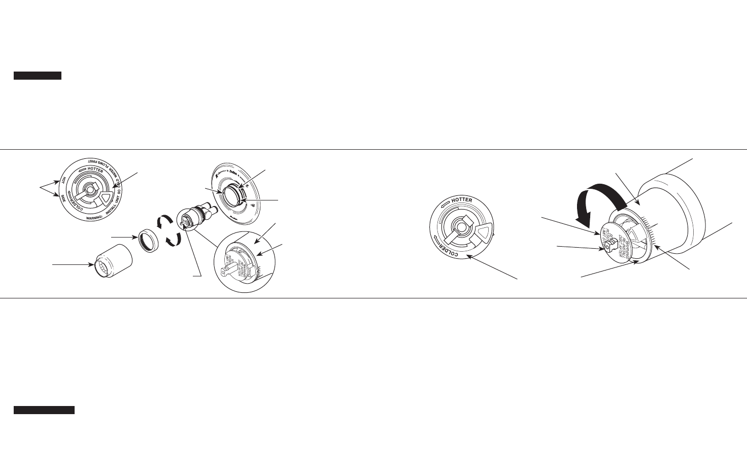
A. REPLACE SINGLE CONTROL CARTRIDGE WITH WHITE COLOR UPPER CAP (SEE FIGURE BELOW).
1.
Antes de comenzar, lea completamente las instrucciones y
familiarícese con las ilustraciones. Se recomienda un plomero para realizar
la instalación.
2.
¡ADVERTENCIA! CIERRE EL SUMINISTRO DE AGUA ANTES DE
DESARMAR LA VÁLVULA DE LA BAÑERA/DUCHA.
3.
Retire la manija.
Para una manija de perilla, quite el botón y el tornillo de la
manija. Para manija de palanca o monomando, retire el tornillo de ajuste al
costado de la manija.
4.
Hale la manga externa (C). Luego, en caso de ser necesario, deslice la manga
del anillo en O (D) hacia usted hasta que se detenga sobre la sección elevada
de latón (E) en el cuerpo de la bañera/ducha. No hale la manga del aro-O sobre
la sección de latón. NOTA: cuando se vuelva a instalar la manga, se deslizará
sobre este anillo en O.
5.
¡ASEGÚRESE DE QUE EL SUMINISTRO DE AGUA
ESTÉ CERRADO!
6. Desatornille el sombrerete de latón (F).
7. ¡ADVERTENCIA! Fíjese en la posición del lado caliente del cartucho marcado
“HOT SIDE” – lado caliente. Vuelva a instalar la manija en la espiga de latón (H)
y gire hacia la derecha en sentido de las manecillas del reloj mientras levanta
el cartucho de las dos muescas a los costados del cuerpo. Si el cartucho no se
puede quitar a mano después de girar y levantar, entonces retire la manija y
agarre suavemente la espiga de la válvula con un alicate y retire el cartucho.
8.
¡AVISO! No gire la Tapa y el cubierta inferior del cartucho nuevo para
desarmarlo. Si los mismos son separados por algún motivo, asegúrese de
cerrarlos de vuelta nuevamente haciéndolos girar hasta que queden
abrochados. ¡ADVERTENCIA! Nunca desarme el cubierta inferior.
9.
Instale el cartucho con la etiqueta con las palabras “HOT SIDE” en la tapa
(B) en el lado de la entrada del agua caliente (vea el Paso 7).
Introduzca el car-
tucho hasta que esté bien asentado y las lengüetas sobre la pieza cilíndrica blanca
estén plenamente engranadas en las muescas en el cuerpo de latón/bronce (I).
10. Ensamble nuevamente el sombrerete de latón (F).
Apriete bien a mano bien.
11. Deslice sobre la manga exterior (C) (vea el paso 4).
12.
IMPORTANTE:
Revise la instalación adecuada del RLS (A) en el cartucho nuevo
siguiendo los pasos B.
13. Vuelva a instalar la manija.
14.
LIMPIE CON AGUA SU SISTEMA. Coloque la manija en la posición completa
de "mezcla de caliente y frío". Abra el suministro de agua. Revise en busca de
filtraciones, y permita que las líneas de suministro se limpien con agua por un
minuto sin mover la manija. Si usted tiene una regadera, desvíe el agua hacia
la misma y permita que se limpie con agua por 30 segundos. Esto eliminará
cualquier desperdicio de las líneas de suministro que puedan dañar las partes
internas de la llave y crear filtraciones. ¡SEA SEGURO! Después de haber
terminado con la reparación, gire la válvula de la bañera/ducha para asegurarse
de que primero fluye el agua fría. En caso contrario vea el paso 7.
1st Position
Posición Primera
Hotter
Más Caliente
Rotational Limit Stop
Tope de Límite de Totacional
Stem
Unidad de la Espiga
Disc
Disco
IMPORTANTE: El Ajuste del Tope que Limita la Rotación se usa para controlar
la cantidad de agua caliente disponible de manera que, si ajustado
apropiadamente, el usuario no se quemará si la manija se gira accidentalmente
completamente a “hot” (“caliente”) cuando una persona se está duchando o
llenando la bañera. La primera posición permite que la MÍNIMA de agua
caliente se mezcle con la fría en el sistema. En la primera posición el agua
estará lo más fría posible cuando la manija se gira completamente a caliente.
Mientras que mueve el Ajuste del Tope que Limita la Rotación en dirección
contraria a las manecillas del reloj, progresivamente aumentará, más y más,
el agua caliente en la mezcla. La última posición a la izquierda es la de mayor
cantidad de agua caliente en la mezcla, y tiene el mayor riesgo de lesión por
quemadura si alguien accidentalmente abre la manija de la válvula
completamente a la posición caliente mientras que se baña o llena la bañera.
ADVERTENCIA: En algunos casos, ajustar el Ajuste del Tope que Limita la Ro-
tación en la posición más caliente (completamente en el sentido contrario a la
dirección de las manecillas del reloj) puede resultar en lesión por quemadura.
Es necesario ajustar el Tope que Limita la Rotación de manera que el agua
que sale de la válvula no queme o escalde al usuario cuando la manija de la
válvula se gira al lado caliente.
• De acuerdo con la mayoría de los estándares de la industria, la tempera-
tura máxima permisible del agua que sale es 120°F (Sus códigos locales
de plomería pueden requerir una temperatura de agua menor de 120°F).
• El Tope que Limita la Rotación puede requerir el ajuste estacional si la
temperatura del agua cambia. Por ejemplo, durante el invierno, la tempera-
tura del agua fría es más fría que durante el verano resultando en
temperaturas variadas en el agua de salida. Una temperatura de agua
para un baño o ducha confortable típicamente es entre 90°F - 110°F.
• Deje que el agua corra de manera que el agua fría esté lo más fría posible
y la caliente esté lo más caliente posible. Coloque la manija en la espiga
y gire la manija en dirección contraria a las manecillas del reloj hasta que
la manija pare.
• Coloque el termómetro en un vaso plástico y sosténgalo bajo el chorro
de agua. Si la temperatura de agua está por encima de 120°F el tope que
limita la rotación debe ajustarse otra vez moviéndolo en sentido de las
manecillas del reloj para reducir la temperatura del agua de salida de la
válvula a menos de 120°F o para que cumpla con los requisitos de sus
códigos locales de plomería.
• Para ajustar la temperatura del agua que sale de la válvula, hale
el disco otra vez a la posición donde se puede remover el Tope del
Límite Rotacional y reajuste el engranaje de los dientes a la posición
para la temperatura deseada. Al mover en dirección de las man
ecillas del reloj reducirá la temperatura del agua de salida, y al con-
trario aumentará la temperatura del agua de salida. El cambio de
temperatura por cada diente (muesca) puede ser de 4°F-16°F depen-
diendo de la condición del agua de entrada. Si es necesario repítalo.
Presione el disco hasta que está asentado completamente.
ADVERTENCIA: Si no reinstala el Disco después de hacer el ajuste
del Tope del Límite Rotacional pudiera escaldarse con agua
demasiado caliente.
• ASEGÚRESE QUE EL AGUA FRÍA FLUYA DE LA VÁLVULA
PRIMERO. ASEGÚRESE QUE EL AGUA QUE FLUYE DE LA VÁLVULA
EN LA POSICIÓN MÁS CALIENTE POSIBLE NO EXCEDA
120°F O EL MÁXIMO PERMITIDO POR SUS CÓDIGOS LOCALES
DE PLOMERÍA.
(A) Rotational Limit Stop
(A)
Tope de Límite de Rotacional
(B) "HOT SIDE"
Lettering
(B) Palabras
"HOT SIDE"
(D) Sleeve O-Ring
(D)
Junta Tórica de la Manga
(C) Sleeve
(C)
Manga
(E) Raised Brass Section
(E)
Sección Levantada de Bronce
(F) Brass Bonnet
(F)
Tuerca Tapa de Bronce
(A) Rotational Limit Stop
(A)
Tope de Límite de Rotacional
HOTTER
MÁS CALIENTE
COLDER
MÁS FRÍA
Front View
Vista de Frente
(H) Valve Stem
(H)
Espiga de la válvula
White Cap
Pieza cilíndrica/aro de remate
White Cap
Pieza cilíndrica/aro de remate
sWARNING!
s ¡ADVERTENCIA!
(I) Notch on Brass Body
(I)
Muesca en el cuerpo de latón
A. CAMBIE EL CARTUCHO DE UN SOLO CONTROL CON UN CILINDRO O ARO DE REMATE SUPERIOR BLANCO (VEA EL DIBUJO A CONTINUACIÓN).
B. EL AJUSTE DEL TOPE DEL LÍMITE ROTACIONAL:


 (12 pages)
 (6 pages)
 Manymanuals.com
 Manymanuals.de
 Manymanuals.fr
 Manymanuals.it
 Manymanuals.pl
 Manymanuals.cz
 Manymanuals.es
 Manymanuals-pt.com
Comments to this Manuals