Delta RMC101 User Manual Page 39
- Page / 68
- Table of contents
- BOOKMARKS
- Startup Guide 1
- Version 2.3 2
- February 25, 2010 2
- Contents 3
- Overview 5
- Obtaining a Manual 6
- Getting Started 7
- The RMCWin Display 8
- Index/stored 9
- Command Table 9
- Index/configuration/MDT 10
- Index/configuration/SSI 10
- Test Actuator Motion 11
- deltamotion.com 12
- Tuning the System 13
- Step-by-Step Example 14
- Communications 14
- Features of the RMC100 15
- S Curves 16
- Splines 16
- Gearing 16
- Pressure Regulating Mode 17
- Quick Mode 17
- Programming 18
- Diagnostic Tools 19
- Command Log 20
- Status Words 20
- I/O Bit Monitor 20
- Parameter Error List 20
- Stored Commands 21
- RMC100 Modules 23
- Communications Choices 24
- Profibus (-PROFI) 25
- Modbus Plus (-MB+) 25
- Serial (-SERIAL) 25
- DI/O (-DI/O) 25
- 27 27
- 29 29
- Analog Input (-An) 31
- Index/ digital i/o /sensor 32
- 33 33
- Appendix A: Wiring 35
- Voltage Feedback Transducers 36
- Current Feedback Transducers 36
- RS422 signals 37
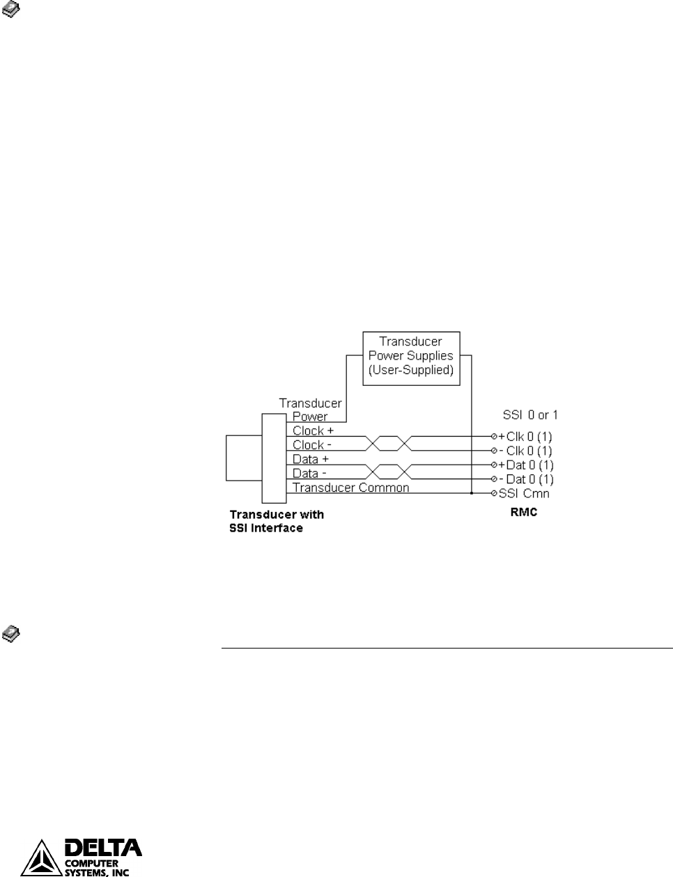
- Index/wiring/SSI 39
- Index/wiring/quadrature 39
- Encoder Wiring 40
- Drive Output Wiring 41
- Fault Input Wiring 41
- Enable Output Wiring 41
- Wiring the Stepper Module 42
- Stepper Output Wiring 43
- Input Wiring 44
- Appendix B: Tuning 45
- Tuning a Position Axis 46
- 47 47
- Tuning a Torque Motor 48
- 49 49
- Position/Pressure Setup 50
- 51 51
- 53 53
- Index/position-pressure 55
- 57 57
- Appendix C: An Example 59
- Calibration. The following 61
- 63 63
- 65 65
- 67 67
Related products and manuals for Sensors Delta RMC101
 (951 pages)
(9 pages)
(34 pages)
(4 pages)
(22 pages)
(150 pages)
(105 pages)
(951 pages)
(9 pages)
(34 pages)
(4 pages)
(22 pages)
(150 pages)
(105 pages)
© 2020, manymanuals.com. All rights reserved. | 3.985 s |
 Manymanuals.com
 Manymanuals.de
 Manymanuals.fr
 Manymanuals.it
 Manymanuals.pl
 Manymanuals.cz
 Manymanuals.es
 Manymanuals-pt.com
Comments to this Manuals