Delta SHOPMASTER GR250 Instruction Manual Page 7
- Page / 12
- Table of contents
- BOOKMARKS
- 6" Variable Speed 1
- Grinder / Sharpener 1
- GENERAL SAFETY RULES 2
- SAVE THESE INSTRUCTIONS 3
- Refer to them often 3
- MOTOR SPECIFICATIONS 4
- GROUNDING INSTRUCTIONS 4
- POWER CONNECTIONS 4
- OPERATING INSTRUCTIONS 5
- GRINDER PARTS 6
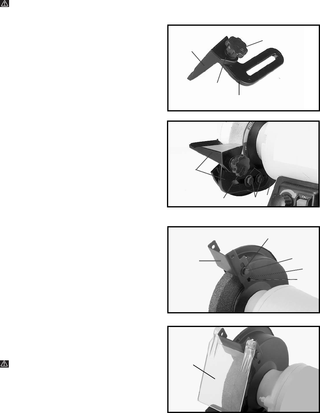
- ASSEMBLY 7
- STARTING AND 8
- STOPPING GRINDER 8
- VARIABLE SPEED 9
- FLEXIBLE LAMP 9
- GRINDING WHEELS 9
- CHANGING GRINDING 10
- WRENCH STORAGE 10
- ACCESSORIES 12
Related products and manuals for Straight grinders Delta SHOPMASTER GR250
 (18 pages)
 (44 pages)
 (6 pages)
© 2020, manymanuals.com. All rights reserved. | 1.496 s |
 Manymanuals.com
 Manymanuals.de
 Manymanuals.fr
 Manymanuals.it
 Manymanuals.pl
 Manymanuals.cz
 Manymanuals.es
 Manymanuals-pt.com
Comments to this Manuals