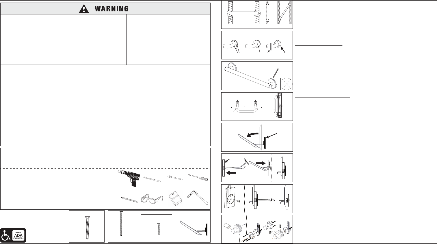
WOOD SCREW (6)
1/4-20 x 3”
Machine Screw (1)
10-24 x 6mm
Machine Screws(3) Wall Anchor (1)
CP11538
8.07.13
©2013 Liberty Hardware Manufacturing Corporation, A MASCO COMPANY
140 Business Park Drive • Winston-Salem, NC 27107
www.libertyhardware.com • Made in China/Hecho en China/Fabriqué Chine
1-800-542-3789
Safety Bar Installation Instructions
PARTS SUPPLIED:
Phillips Screw Driver
Safety glasses
Pencil
Drill 1-inch Drill Bit
3/16-inch Drill Bit
Stud Finder
1-inch Carbide Tip Drill Bit
5/16-inch Carbide Tip Drill Bit
3/8-inch Drive Ratchet
TOOLS REQUIRED:
• 3/8-inch Power Drill
• 1-inch drill bit or hole saw (carbide tip bit for hard surfaces like Ceramic Tile.
• 3/16-inch Drill Bit (to drill pilot hole for installation of Lag screw into wood wall stud)
• 5/16-inch Carbide Tip Drill Bit (if drilling through ceramic tile)
• 7/16-inch HEX Socket with 3/8-inch Drive Ratchet
• #2 Phillips screwdriver
• Stud finder
• Pencil
• Safety glasses
ANCHOR REQUIREMENTS:
• Requires a 3 1/2” space behind the wall and works in the following substrates:
• 1/2” or 5/8” Drywall (ONLY use on 5/8” drywall for commercial applications)
• 1/2” or 5/8” Drywall with Tile
• 1/2” or 5/8” Drywall with Marble/Stone
BEFORE INSTALLING:
1. Remove the parts and products from package. If concealed mount Grab Bar is used, move
cover plates away from mounting holes. (Fig. 2)
2. Determine the location of the product and where you want to install it.
3. Place product on the wall at desired location. If mounted horizontally, check that the product
is level.
4. Use a pencil and mark the centers on each side of the product for the mounting locations.
(Fig. 3)
5. Location: A stud finder should be used to verify if there are any studs behind the marked
locations. Install the product using stud-mounting directions if a stud is available. If a stud is
not located within the area where the supplied anchor will be installed then use the non-stud
mounting directions.
STUD-MOUNTING DIRECTIONS:
6. Put on safety glasses before starting.
7. Use the 3/8-inch power drill and 7/64-inch drill bit to drill all holes into the wall and wood
wall stud(s) at the marked positions. NOTE: If installing Grab Bar over ceramic tiles, the
1/4-inch carbide tip drill bit will be needed for drilling through the tile, in order to prevent
damage to the tiles. Drill pilot holes through the tiles by using a 1/4-inch carbide tip drill bit.
Once a hole has been drilled through the ceramic tiles, use the 7/64-inch drill bit to drill a
pilot hole in the wood wall stud itself.
8. Repeat Step 7 for opposite end of the Grab Bar.
9. Place Grab Bar on wall, aligning mounting holes with the holes in the wall.
10. Insert the wood screws provided into one end of the Grab Bar. Screw into wall and wall stud
(HAND TIGHTEN ONLY). (Fig. 4)
11. Securely tighten all mounting wood screws with a screw driver.
12. If concealed mount Grab Bar is used, move cover plates over mounting holes and firmly
press against the wall. (Fig. 2)
NON-STUD MOUNTING DIRECTIONS:
6. Put on safety glasses before starting.
7. Use the 3/8-inch power drill and the 1-inch drill bit or hole saw to drill a one-inch hole
precisely at each of the marked center positions from the previous step. NOTE: If installing
the product over ceramic tile or other hard surface the carbide tip drill bit or hole saw will be
needed.
8. Clean the wall surface of any dust or debris.
9. Place the flange plate on the wall and rotate to the correct angle to align the holes on the
grab bar at the desired position. Once the location and angle is aligned, place a mark at the
top of the flange plate to note the upward direction. Next, peel and remove (1) piece of
protective strips from the circle piece of tape. Place the tape on the end of the arm and
adhere the arm with the bar in the upward direction to the back side of the flange plate. The
arm should sit inside ring. *It is important the arm always be upright.*
10. Peel and remove (1) piece of protective strips from tape on the supplied wall anchor brace
bar. The tape is necessary to allow the supplied wall anchor brace bar to adhere to the back
side of the wall for placement. (This will ensure that the bar will stay upright during
installation.)
11. Get supplied anchor, flip the bar downward at the end of the arm. The bar should be tilted
up only slightly. (Fig. 5)
12. Hold the flange of the supplied anchor and insert the bar into the wall. The bar should have
the “UP” arrow pointing upward when installing into the wall.
13. Once the bar is completely inside the wall, pull outward/back on the flange and ensure the
bar tilts upward behind the wall and straightens upright. The bar should be resting on the
back side of the wall and pointing upward with the longest side at the top. (Fig. 6)
14. Hold on tightly to the flange and keep pressure on the bar behind the wall to ensure that the
bar stays upright with the longest part of the bar pointing upward. The bar behind the wall
must always be upright and the longest part must be pointing upward for the anchor to
perform properly.
15. As you hold the flange and apply pressure to the bar by pulling outward, insert a 3” machine
screw into the center hole of the flange. Then align the machine screw with the threaded
insert in the bar and tighten. (Fig. 7)
16. Turn and tighten the screw while applying pressure on the bar to keep it upright. Tighten the
screw till the flange plate is flush against the wall and is secure.
17. Tighten the flange with the #2 Phillips screw driver. Ensure the flange is tight and secure
against the wall without any movement.
18. On opposing side use the STUD-MOUNTING DIRECTIONS 7-9 listed above.
19. Align the adapter with the installed anchor, then take the product and align the product with
the adapter/installed wall anchor and ensure holes align.
20. Use the 10-24 machine screws that are supplied with the wall anchor to fasten the product
to each wall anchor. Three (3) machine screws are needed to fasten the product to the wall
anchor and they need to be securely fastened with a #2 Phillips screwdriver. (Fig. 8)
THE FOLLOWING STEPS REQUIRE DRILLING INTO
THE WALL.
When drilling into the wall, exercise care to
avoid any electrical wiring or plumbing that may be
located behind the wall. Damaged electrical wiring can
cause electrical shock and/or fire. Since older homes do
not always fall in line with current housing codes and
requirements, know where internal wall wiring is located
so that no wires will interfere with your installation.
PROPER INSTALLATION IS EXTREMELY
IMPORTANT. IF IN DOUBT, INSTALLATION
SHOULD BE DONE BY A QUALIFIED
PROFESSIONAL.
GRAB BAR MAY NOT PROVIDE DESIGNED AMOUNT OF SUPPORT UNLESS
THESE INSTALLATION INSTRUCTIONS ARE STRICTLY FOLLOWED.
For proper installation, at least one end of Grab Bar MUST be positioned over a wall
stud. For solid support, at least two (2) of the three (3) screws on the end of the Grab
Bar MUST go through the wallboard or tile and be tightly secured into the wall stud.
Given standard stud sizes, only two (2) of the three (3) screws may screw into the wall
stud. Grab Bar may be installed vertically, horizontally or at an angle, so long as at
least two (2) of the three (3) mounting screws on one end of the Grab Bar are secured
into a wall stud (see Figure 1). Locate the wall stud(s) behind the wall before
beginning installation (a stud finder can be obtained from a hardware store).
Fig. 3
Fig. 5
Fig. 8
FRONT VIEW
VERTICAL MOUNT
FRONT VIEW
ANGLE MOUNT
WOOD
WALL
STUD
NORMALLY
16" CENTER-TO-CENTER
FRONT VIEW
HORIZONTAL MOUNT
Fig. 1
WALLBOARD
WALLBOARD
Fig. 4
EXPOSED MOUNT GRAB BAR CONCEALED MOUNT GRAB BAR
Fig. 2
Fig. 6
1 2 3
Fig. 7
1 2 3
Flange
Flange
Drywall
WOOD
WALL
STUD
WOOD
WALL STUD
WOOD
WALL STUD
TOP VIEW
HORIZONTAL MOUNT
GRAB
BAR
GRAB
BAR
SIDE VIEW
VERTICAL MOUNT
WOOD
SCREW
Stud Installation Non-Stud Installation
Cover Plate
Mounting
Holes
1 2 3
CAUTION AND SAFETY WARNINGS:
• DO NOT install this product without first reading and understanding this instruction sheet. If you are unable to understand these Warnings and
Instructions, contact a professional or technical personnel for assistance before attempting to install this product - otherwise, injury may occur.
• After ANY adjustments, repair or service and BEFORE use, make sure that all attaching hardware is tightened securely.
• Assist Bars add security for bath and commode areas if attached as instructed. Location, size, and angle of bars should be determined by a
qualified professional to provide optimum safety and function.
• Use EXTREME caution on wet tub or floor surfaces.
• Users with limited physical capabilities should be supervised or assisted in bath and commode areas, even when using Assist Bars.
• This Assist Bar can provide support and increased stability for an individual weighing up to 300 pounds. Assist Bars are NOT designed to
support the total weight of an individual. Use the bar for assistance ONLY.
• Be sure Assist Bars are correctly and securely installed. NEVER use Assist Bars if any looseness is noted.
• (For Anchor Mount) DO NOT install supplied wall anchors into wallboard less than 1/2” or greater than 2 1/2” thick.
• (For Anchor Mount) DO NOT install supplied wall anchors into wallboard that has been subjected to water damage or decay.
• (For Anchor Mount) DO NOT install supplied wall anchors into a wood stud.
• Locate studs prior to drilling. Determine if plumbing, electrical or other obstructions, i.e. beads of adhesive ribbing, as in some tub surrounds,
are contained behind the wall.
• If mounting to an uneven surface, use silicone to fill any gaps between surface and mounting plate.
• Apply a bead of silicone sealant designed for wet applicators to the back face of both assist bar mounting flanges. This will prevent water from
bleeding through the mounting holes potentially damaging the wall board.


 (2 pages)
 (4 pages)
 (1 pages)
 Manymanuals.com
 Manymanuals.de
 Manymanuals.fr
 Manymanuals.it
 Manymanuals.pl
 Manymanuals.cz
 Manymanuals.es
 Manymanuals-pt.com
Comments to this Manuals