Delta 50-665 Instruction Manual
Browse online or download Instruction Manual for Unknown Delta 50-665. Delta 50-665 Instruction manual User Manual
- Page / 12
- Table of contents
- BOOKMARKS
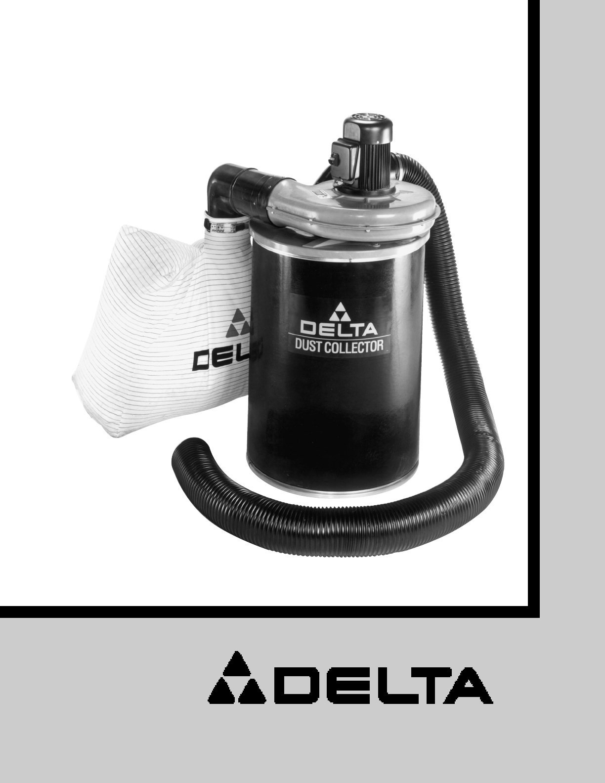
- /2 H.P. Dust Collector 1
- TABLE OF CONTENTS 2
- IMPORTANT SAFETY RULES 3
- IMPORTANT SAFETY RULES FOR 4
- DUST COLLECTORS 4
- INTRODUCTION 4
- SAVE THESE INSTRUCTIONS 4
- UNPACKING 5
- ASSEMBLY 6
- ON/OFF SWITCH 10
- CONNECTING DUST COLLECTOR TO 10
- POWER SOURCE 10
- MAINTENANCE 11
- M O TO R MAINTENANCE 11
- Two Y ear Limited Warranty 12
Summary of Contents
INSTRUCTION MANUAL11/2 H.P. Dust Collector(Model 50-665)D ATED 8-8-99 PA RT NO. 1342493'Delta International Machinery Corp. 1999Shown with Access
10ON/OFF SWITCHThe ON/OFF switch is conveniently located on the sideof the motor . To turn the dust collector ON push theswitch (A) Fig. 22, upwar
11LOCKING SWITCH IN THE OFF POSITIONW e suggest when the dust collector is not in use that the ON/OFF switch be locked in the OFF position. This
Delt a Building Trades and Home Shop MachineryTwo Y ear Limited WarrantyDelt a will rep air or replace, at it s expense and at it s option, any Delt a
2TABLE OF CONTENTSSAFETY RULES...
3IMPORTANT SAFETY RULESW oodworking can be dangerous if safe and proper operating procedures are not followed. As with all machinery, there are cert a
4IMPORTANT SAFETY RULES FORDUST COLLECTORSINTRODUCTIONDust Collectors work by moving large volumes of air at lower suction pressures than vacuumcleane
51. Blower and Motor Assembly2. Vacuum Hose3. Cylinder4. Dust Bag Elbow5. Hose Clamps (2)6. Dust Bag7. Dust Bag Clamp8. Hardware for Mounting Inlet El
6ASSEMBLY1. Place gasket (A) Fig. 3, on bottom of motor andblower assembly (B). Align four holes in gasket withholes in motor and blower assembly and
7Fig. 7Fig. 8Fig. 9Fig. 1 1Fig. 105. Position the remaining inlet elbow (K) Fig. 8, at theunderside of dust collector lid (C) as shown. Align themount
8CAUTION: Never remove safety grid for any reasonexcept to perform maintenance procedures. There isa high speed blower wheel inside the blower housing
9Fig. 1710. Insert the bag clamp (Z) Fig. 16, through the loop s ofthe dust bag (A).11. Clamp dust bag (A) Fig. 17, to bag elbow (V) asshown by fasten
Related products and manuals for Unknown Delta 50-665
 (1 pages)
(36 pages)
(1 pages)
(36 pages)

 (2 pages)

 (2 pages)
(2 pages)
(2 pages)
(2 pages)
(2 pages)
(2 pages)
(2 pages)
 (2 pages)
© 2020, manymanuals.com. All rights reserved. | 0.243 s |
 Manymanuals.com
 Manymanuals.de
 Manymanuals.fr
 Manymanuals.it
 Manymanuals.pl
 Manymanuals.cz
 Manymanuals.es
 Manymanuals-pt.com
Comments to this Manuals