Delta 50-866 User Manual Page 7
- Page / 16
- Table of contents
- BOOKMARKS
- 5 H.P. Dust Collector 1
- GENERAL SAFETY RULES 2
- SAVE THESE INSTRUCTIONS 3
- Refer to them often 3
- UNPACKING AND CLEANING 4
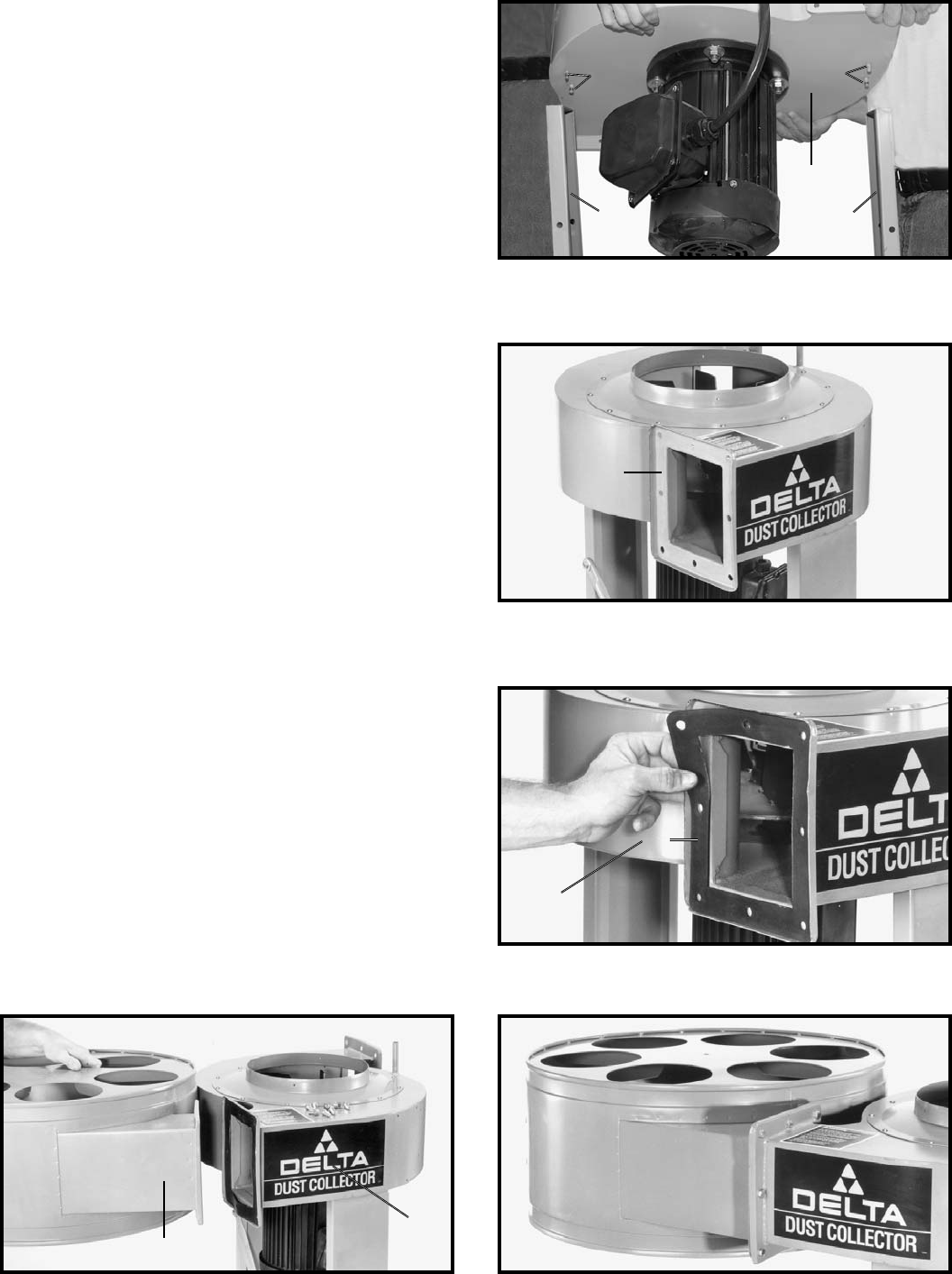
- ASSEMBLY 6
- ASSEMBLING DRUM 8
- SUPPORT POSTS TO 8
- BASE AND DRUMS 8
- CONNECTING MACHINE 12
- TO POWER SOURCE 12
- DUST INTAKE PORT 13
- MAINTENANCE 14
- MOTOR MAINTENANCE 14
- ACCESSORIES 15
- • DELTA SERVICE CENTERS 16
- • DELTA) 16
Related products and manuals for Vacuums Delta 50-866
 (12 pages)
 (36 pages)
 (48 pages)
© 2020, manymanuals.com. All rights reserved. | 1.744 s |
 Manymanuals.com
 Manymanuals.de
 Manymanuals.fr
 Manymanuals.it
 Manymanuals.pl
 Manymanuals.cz
 Manymanuals.es
 Manymanuals-pt.com
Comments to this Manuals