3. Connect the input control signal:
• Terminal 102 from the master actuator to
Terminal 102 on the slave actuator
• For D24-210 and -280 models, connect the input
control signal to the common, CW, and CCW
terminals on both the master and slave actuators.
(See Figure 7).
• Terminal 103 from the master actuator to
Terminal 103 on the slave actuator
b. When mounting two actuators back-to-back on
the same shaft, connect:
• For DM24-140, -210, and -280 Models, connect
the control signal to the master actuator and
connect 24 VAC/VDC power to both the master
and slave actuators.
• Terminal 101 from the master actuator to
Terminal 102 on the slave actuator
• Terminal 102 from the master actuator to
Terminal 101 on the slave actuator
IMPORTANT: For proper tandem operation,
do not connect the control input to the slave unit.
Note:
• Terminal 103 from the master actuator to
Terminal 103 on the slave actuator
Set the master actuator jumpers on the
DM24-140, -210, and -280 models according to the
action and signal range desired before proceeding.
(Refer to Figure 8 and the Setup and Adjustments,
Calibration section.)
Note: The total wire length for these connections
may be up to 30 ft (9 m).
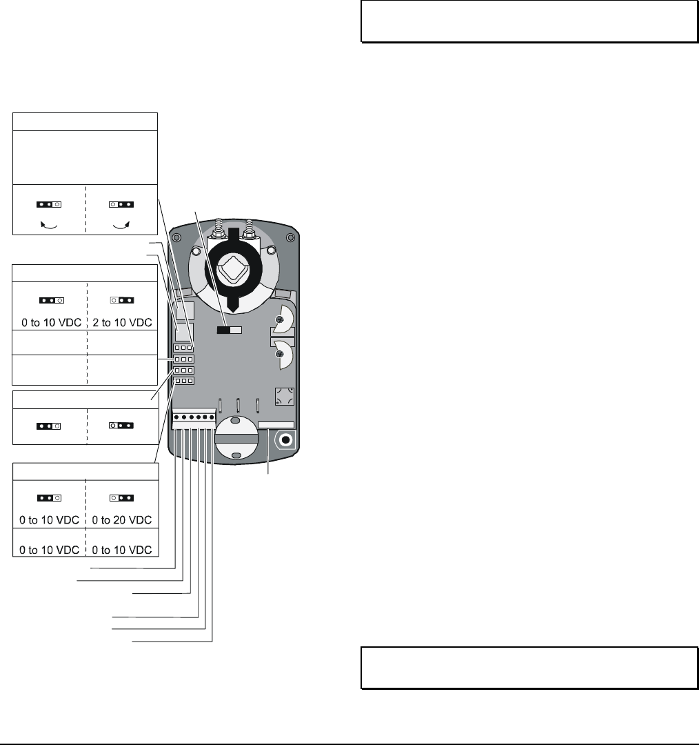
Span Potentiometer
Zero Potentiometer
Adjustable
Fixed
Jumper W3*
Factory Set
* -Z or -Z-A Models Only
Jumper W2
Factory Set
Voltage Input
0-10 VDC
Feedback Ouput
0 to 20 mA 4 to 20 mA
2-10 VDC
Current Input
Term i na l
Block 1
101 102 103
Jumper W1
Direct Acting (DA)
Reverse Acting (RA)
Rotation Direction with
Increasing Signal
Factory Set
(CCW) RA
(CW) DA
1 Common
2 Power
3 Calibration Ouput
(-Z or -Z-A Models Only)
4 Current Input
5 Voltage Input
6 Feedback Output
Note:
Jumpers W1, W2, W3, and W4
have no effect when the actuator
is in the Slave mode.
Master/Slave Jumper
(Shown in the
Master position)
Auxiliary Switches
(See Figure 5.)
Terminal
Block 1
Factory Set
Voltage Input
Jumper W4
Feedback Output
1 2 3 4 5 6
Note:
For current input,
Jumper W4 must
be in the 0 to 10 VDC
position.
101 102
103
4. Make sure of the following if the actuators
configured for tandem operation stall or do not
drive:
• Both actuators have the same torque and
control input.
• One actuator is set as the master and the
other as the slave.
• The control signal is connected to the master
actuator only.
• Terminal 101, Terminal 102, and Terminal 103
are connected properly, as described in
Step 2.
Setup and Adjustments
Calibration
Calibrate only the actuator designated as the master
when using a combination of two D24-210 or -280 or
two DM24-140, -210, or -280 models in tandem.
Direction of Action
In the DA mode, a minimum control signal drives the
actuator to the full CCW position, and a maximum
control signal drives it fully CW. In the RA mode, a
minimum control signal drives the actuator to the full
CW position, and a maximum control signal drives it
fully CCW. To set an actuator for RA, proceed to the
section for the appropriate model.
IMPORTANT: Adjust the rotation range before
changing the direction of action.
Figure 8: Settings on Proportional (DM24) Models
D-70, D-140, D-210, and D-280 Series Electric Non-Spring Return Actuators Installation Instructions 5
 Manymanuals.com
 Manymanuals.de
 Manymanuals.fr
 Manymanuals.it
 Manymanuals.pl
 Manymanuals.cz
 Manymanuals.es
 Manymanuals-pt.com
Comments to this Manuals