Delta 36-L51X Instruction Manual
Browse online or download Instruction Manual for Circular saws Delta 36-L51X. Delta 36-L51X Instruction manual User Manual
- Page / 76
- Table of contents
- BOOKMARKS
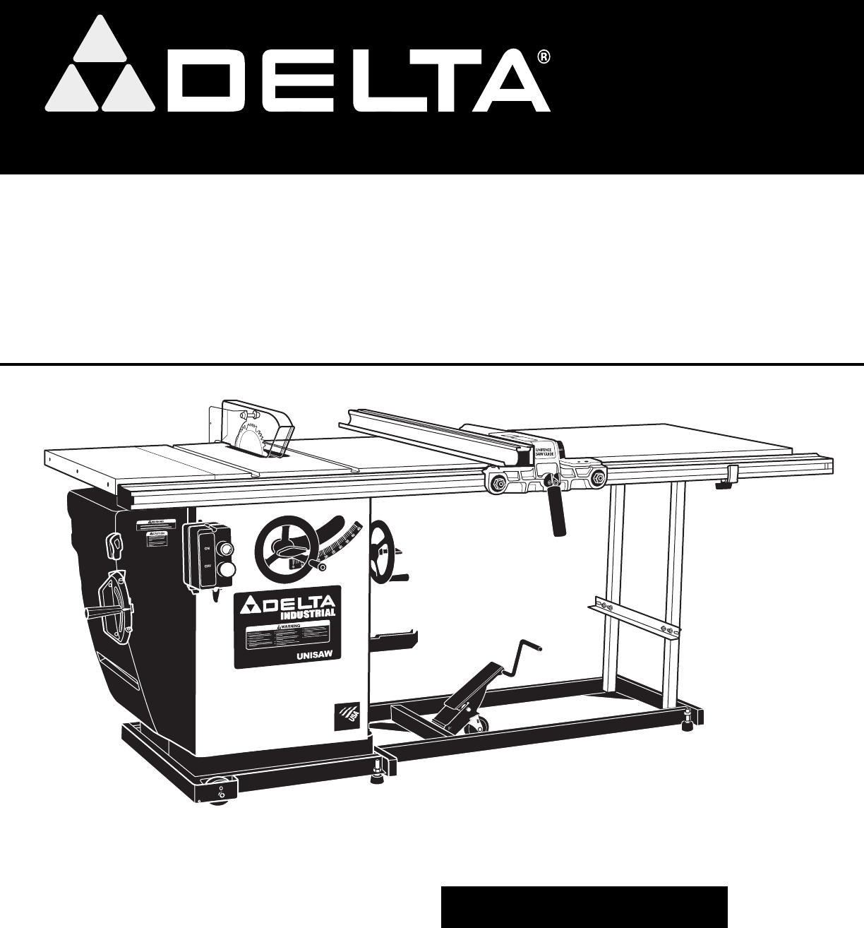
- UNISAW sierra 1
- TABLE OF CONTENTS 2
- IMPORTANT SAFETY INSTRUCTIONS 2
- CALIFORNIA PROPOSITION 65 3
- GENERAL SAFETY RULES 4
- SAVE THESE INSTRUCTIONS 5
- POWER CONNECTIONS 6
- GROUNDING INSTRUCTIONS 6
- CARTON CONTENTS 7
- ASSEMBLY 8
- Fig. 3 Fig. 4 9
- Fig. 12 Fig. 13 11
- Fig. 24 Fig. 25 13
- OPERATION 14
- Fig. 39 Fig. 40 16
- MACHINE USE 18
- Fig. 51 19
- Fig. 48 19
- Fig. 49 19
- Fig. 50 19
- Fig. 52 20
- Fig. 53 Fig. 54 20
- Fig. 65 Fig. 66 23
- TROUBLESHOOTING 25
- MAINTENANCE 25
- ACCESSORIES 25
- WARRANTY 26
- FRANÇAIS 27
- RÈGLES DE SÉCURITÉ GÉNÉRALES 29
- CONSERVER CES DIRECTIVES 30
- CONTENUS DE BOITE 32
- FUNCTIONAL DESCRIPTION 32
- ASSEMBLAGE 33
- RALLONGES 34
- COUVERCLE DU MOTEUR 38
- FONCTIONNEMENT 39
- AJUSTEMENT DE LA TABLE 41
- CHANGEMENT DE LA LAME 42
- UTILISATION DE LA MACHINE 43
- DEPANNAGE 49
- ENTRETIEN 50
- ACCESSOIRIES 50
- GARANTIE 50
- PROPOSICIÓN DE CALIFORNIA 65 52
- NORMAS GENERALES DE SEGURIDAD 53
- MOTOR SPECIFICATIONS 55
- DESCRIPCIÓN FUNCIONAL 56
- CONTENIDO DE CARTON 56
- ENSAMBLAJE 57
- BASES DE EXTENSIÓN 58
- UTILIZAR LA MAQUINA 67
- Fig. 54 69
- MADERA”, y el uso 70
- MANTENIMIENTO 74
- LOCALIZACION DE FALLAS 74
- SERVICIO 74
- GARANTIA 75
- ACCESORIOS 75
- Delta Machinery 76
- 4825 Highway 45 North 76
- Jackson, TN 38305 76
- (800) 223-7278 76
Summary of Contents
www.deltamachinery.com(800) 223-7278 - US(800) 463-3582 - CANADAPenchant À GaucheUNISAW® (10 po)10" Left Tilting UNISAW®Instruction ManualManuel
10LVC "ON/OFF" SWITCHMount the LVC switch bracket (C) Fig. 6 (removed earlier) to the inside of the hole (D) on the left front edge of the e
115. To adjust, loosen the two screws (F) Fig. 12. Adjust the splitter bracket (A) until it is aligned with the inside blade flange (B) Fig. 11. Tig
12Fig. 18Fig. 19Fig. 20Fig. 21Fig. 22Fig. 23PCPMVOGWPYPZABPBC10. Insert the front end of the splitter (P) Fig. 18 inside the splitter mounting bracke
1314. Hold the blade guard and lower the saw blade. Install the table insert (E) Fig. 25 in the open ing of the saw table.15. Place a straight edge (B
14RIP FENCE HOLDER BRACKETSAttach the rip fence holder brackets (A) Fig. 30 to the four holes located in the right hand side of the saw cabinet. Use t
15If the motor continually shuts off due to overloading, contact a qualified electrician.In the event of a power outage (breaker or fuse trip), always
163. Ensure that the tilt-indicator pointer is on the zero mark. Adjust if necessary.4. Turn the blade-tilting handwheel counter-clockwise as far as
17Insert the miter gauge bar into the miter gauge slot. Attach the washer and lock handle (A) Fig. 42.The miter gauge is equipped with adjustable inde
181. Remove the motor cover.2. Place a piece of wood (C) Fig. 46 between the motor and the saw cabinet. NOTE:You may need to raise the saw arbor to
19CROSS-CUTTINGCross-cutting requires the use of the miter gauge to posi tion and guide the work. Before starting the cut, raise the blade so that it
2TABLE OF CONTENTSRead and understand all warnings and operating instructions before using any tool or equipment. Always follow basic safety precauti
20MITERINGMitering (the operation shown in Fig. 52) is the same as crosscutting except that the miter gauge (C) is locked at an angle other than 0°. H
21AFig. 55 Fig. 48 Fig. 48 Fig. 56 Fig. 57 Fig. 582. When the workpiece is past the blade, the work will either st
22Moulding is cutting a shape on the edge or face of the workpiece with a special moulding cutterhead.The moulding head consists of a cutterhead in wh
23The blade guard and splitter assembly cannot be used when dadoing or moulding. It must be removed as described in “USING AN ACCESSORY MOULDING CUTTE
24CONSTRUCTING A FEATHERBOARDFeatherboards are used to keep the work in contact with the fence and table (Fig. 69), and help prevent kickbacks. Dimens
25TROUBLESHOOTINGFor assistance with your machine, visit our website at www.deltamachinery.com for a list of service centers or call the DELTA Machine
26Two Year Limited New Product WarrantyDelta will repair or replace, at its expense and at its option, any new Delta machine, machine part, or machine
FRANÇAIS
28MESURES DE SÉCURITÉ - DÉFINITIONSCe guide contient des renseignements importants que vous deviez bien saisir. Cette information porte sur VOTRE SÉCU
291. POUR SA SÉCURITÉ PERSONNELLE, LIRE LA NOTICE D’UTILISATION, AVANT DE METTRE LA MACHINE EN MARCHE, et pour aussi apprendre l’application et les
3It is important for you to read and understand this manual. The information it contains relates to protecting YOUR SAFETY and PREVENTING PROBLEMS. Th
30RÈGLES SPÉCIFIQUES ADDITIONNELLES DE SÛRETÉL’inobservation de ces règles peut conduire à des blessures graves.CONSERVER CES DIRECTIVES.Les consulter
311. Toutes les machines avec cordon mis à la terre: Dans l’éventualité d’un mauvais fonctionnement ou d’unepanne, la mise à la terre fournit un tra
32CONTENUS DE BOITECORDON DE RALLONGEEmployez les cordes appropriées de prolongation. S'assurent votre corde de prolongation est en bon état. En
33ASSEMBLAGEPour votre propre sûreté, ne reliez pas la machine à la source d'énergie jusqu'à ce que la machine soit complètement assemblée e
34VOLANT D’INCLINAISON DE LA LAME1. Enfiler une rondelle de plastique (A) fig. 1 sur la tige du volant d’inclinaison de la lame (B). Insérer la clé (
35INTERRUPTEUR MARCHE/ARRÊT À COMMANDE BASSE TENSIONAssembler le support de l’interrupteur à commande basse tension (C) fig. 6 (retiré plus tôt) à l’i
365. Pour ajuster, desserrer les deux vis (F) fig. 12. Régler le support du couteau séparateur (A) jusqu’à ce qu’il s’aligne avec la bride interne de
3710. Insérer l’extrémité avant du couteau séparateur (P) fig. 18 dans le support de montage du couteau séparateur derrière la plaque de fixation et l
3814. Tenir le protège-lame et abaisser la lame de la scie. Insérer la pièce d’insertion de la table (E) fig. 25 dans l’ouverture de la table de la s
39SUPPORTS DE RANGEMENT DU GUIDE LONGITUDINALFixer les supports de rangement du guide longitudinal (A) fig. 30 aux quatre trous logés du côté droit de
4GENERAL SAFETY RULESFailure to follow these rules may result in serious personal injury.SAVE THESE INSTRUCTIONS. Refer to them often and use them to
40Si le moteur éteint continuellement en raison de surcharger, contacter un électricien qualifié. En cas de panne d’électricité (disjoncteur désarmé o
413. S’assurer que le pointeur, qui indique le degré d’inclinaison, pointe sur le repère zéro. Régler le cas échéant.4. Tourner le volant d’inclina
42Insérer la barre du guide d’onglet dans la rainure du guide. Enfiler la rondelle et fixer la poignée de verrouillage (A) fig. 42.Le guide d’onglet e
431. Retirer le couvercle du moteur.2. Insérer une pièce de bois (C) fig. 46 entre le moteur et l’armoire de la table de la scie. REMARQUE : il sera
44TRONÇONNAGELe tronçonnage nécessite l’utilisation de la jauge à onglet pour positionner et guider l’ouvrage. Avant de débuter le tronçonnage, lever
45DÉCOUPE À L’ONGLETLa découpe à l’onglet (fig. 52) est semblable au tronçonnage sauf que la jauge à onglet (C) est verrouillée à un angle autre que z
46SCIAGE SUR LE LONG EN BISEAULe sciage sur le long en biseau (fig 59) est similaire au sciage sur le long sauf que l’angle de biseau est réglé à un a
47Moulurer est tout simplement la coupe d’une forme sur le bord ou la face d’un ouvrage à l’aide d’une fraise à moulurer spéciale.La fraise à moulurer
48L’ensemble pare-main/couteau separa-teur ne peup ps-tre utilise pour le rainutages ou les coupes a la fraise a moulurer. Il doit - tre retire tel q
49FABRICATION D’UNE PLANCHE EN ÉVENTAILPlanches en éventa est utilisé pour garder le travail dans le contact avec la clôture et la table (fig. 69), et
5SAVE THESE INSTRUCTIONS. Refer to them often and use them to instruct others. FAILURE TO FOLLOW THESE RULES MAY RESULT IN SERIOUS PERSONAL INJURY.ADD
50ENTRETIENGARDER LA MACHINE PROPREDégager régulièrement toutes les conduites d’air avec de l’air comprimé sec. Toutes les pièces en plastique doivent
ESPAÑOL
52Lea y entienda todas advertencias y las instrucciones operadoras antes de utilizar cualquier instrumento o el equipo. Cuando se usa instrumentos o e
53NORMAS GENERALES DE SEGURIDAD1. PARA SU PROPIA SEGURIDAD, LEA EL MANUAL DE INSTRUCCIONES ANTES DE UTILIZAR LA MÁQUINA. Al aprender la aplicación, l
54NORMAS ESPECÍFICAS ADICIONALES DE SEGURIDADSi no se siguen estas normas, el resultado podría ser lesiones personales graves.1. NO OPERE ESTA MÁQUIN
551. Todas las máquinas conectadas con cordón conectadas a tierra: En caso de mal funcionamiento o avería, la conexión a tierra proporciona una rut
56CORDONES DE EXTENSIÓNUtilice cordones de extensión apropiados. Asegúrese de que el cordón de extensión esté en buenas condiciones y de que sea un co
57ESTIMACIÓN DEL TIEMPO DE ENSAMBLAJEAssembly for this machine takes approximately two to three hours.1HERRAMIENTAS DE ENSAMBLAJE REQUERIDASLlave hexa
58VOLANTE DE INCLINACIÓN DE LA HOJA1. Coloque una arandela de fibra (A) Fig. 1, en el eje del volante de inclinación de la hoja (B). Instale la llave
59INTERRUPTOR DE "ENCENDIDO/APAGADO" (ON/OFF) LVCColoque el soporte del interruptor LVC (C) Fig. 6, (que retiró anteriormente) en el interio
6A separate electrical circuit should be used for your machines:FOR SINGLE PHASE UNITS (EXCEPT THE FIVE HORSEPOWER): This circuit should not be less t
605. Para ajustar, desajuste los dos tornillos (A), Fig. 12. Ajuste el soporte del hendedor (A) hasta que esté alineado con la brida de hoja interna
6110. Inserte el extremo frontal del hendedor (P) Fig. 18, en el interior del soporte de montaje del hendedor detrás de la placa de sujeción del hende
6214. Sujete el protector de la hoja y baje la hoja de la sierra. Instale el inserto para el banco (E) Fig. 25, en la abertura del banco de la sierra
63SOPORTES DEL SUJETADOR DE LA GUÍA DE CORTEConecte los soportes del sujetador de la guía de corte (A) Fig. 30, a los cuatro orificios ubicados a la d
64Si el motor se apaga en forma continua por sobrecargas, comuníquese con un electricista calificado.En el caso de un corte eléctrico (por ejemplo, po
653. Asegúrese de que el indicador de inclinación esté en cero. Ajuste si es necesario.4. Gire el volante de inclinación de la hoja hacia la izquie
66Inserte la barra del calibrador de inglete en la ranura para calibrador de inglete. Coloque la arandela y el mango de bloqueo (A) Fig. 42.El calibra
671. Retire la cubierta del motor.2. Coloque una pieza de madera (C) Fig. 46 entre el motor y el gabinete de la sierra. NOTA: Posiblemente sea neces
68CORTE TRANSVERSALEl corte transversal requiere del uso de un calibrador de inglete para guiar y ubicar la pieza de trabajo en la posición correcta.
69CORTE A INGLETEEl corte a inglete (la operación ilustrada en la Fig. S5) es igual al corte trans-versal, excepto que el calibrador de inglete (C) es
7Permanently connected machines:If the machine is intended to be permanently connected, all wiring must be done by a qualified electrician and conform
70AFig. 55 Fig. 48 Fig. 48 Fig. 56 Fig. 57 Fig. 582. Cuando la pieza de trabajo haya pasado la hoja, se mantendrá
71Se denomina moldura al corte con forma en el borde o en el frente de la pieza, realizado con un cabezal portacuchilla especial para molduras.El cabe
72El ensamble del protector de la hoja y el hendedor no puede ser utilizado al realizar ranuras o mol-duras. Debe ser retirado como se describe en la
73CONSTRUCCIÓN DE UNA TABLA DE CANTO BISELADOLa Fig. S23 ilustra las dimensiones para realizar una tabla de canto biselado típica. El material de la t
74MANTENIMIENTOLOCALIZACION DE FALLASPara obtener asistencia para su máquina, visite nuestro sitio Web en www.deltamachinery.com para tener acceso a u
75GARANTIAUna línea completa de accesorios está disponible de su surtidor de Porter-Cable • Delta, centros de servicio de la fábrica de Porter-Cable
76The gray & black color scheme is a trademark for Porter-Cable Power Tools and Accessories. The following are also trademarks for one or more Por
8ASSEMBLY TIME ESTIMATEAssembly for this machine takes approximately two to three hours.1ASSEMBLYASSEMBLY TOOLS REQUIRED1/8" Hex wrench (supplied
9BLADE-TILTING HANDWHEEL1. Install a fiber washer (A) Fig. 1 on the blade-tilting handwheel shaft (B). Install the key (C) into the shaft keyway.2.
Related products and manuals for Circular saws Delta 36-L51X
 (76 pages)

 (100 pages)
(32 pages)
(84 pages)
(2 pages)
(25 pages)
(6 pages)
(12 pages)
(100 pages)
(32 pages)
(84 pages)
(2 pages)
(25 pages)
(6 pages)
(12 pages)
© 2020, manymanuals.com. All rights reserved. | 0.141 s |
 Manymanuals.com
 Manymanuals.de
 Manymanuals.fr
 Manymanuals.it
 Manymanuals.pl
 Manymanuals.cz
 Manymanuals.es
 Manymanuals-pt.com
Comments to this Manuals