Delta Digital timer User Manual Page 64
- Page / 74
- Table of contents
- BOOKMARKS
- Compliant 2
- CONTENTS PAGE NOS 3
- 2A5DT5 2AJDT0 9
- Cat. No 10
- For ON Delay & 15
- Interval Mode Selection 15
- 6ED 73 T 16
- 7ED 73 T 16
- 40MFS0 40AFS0 40SFS0 17
- 70MDT0 70ADT0 19
- (74SDT0) 20
- STAR DELTA 20
- (70SDT0) 20
- 27B1C3B1 21
- =5s =5s=5s 22
- Digital Timer 23
- BASE MOUNTING 26
- C B 1 27
- Glossary 28
- Operating Modes / Functions 29
- TIME SWITCHES 31
- Time Switch FM Series 32
- Digital Time Switches & 33
- Astronomical Time Switch 34
- Astronomical Time Switches 35
- , OV settings 37
- HOUR METERS & COUNTERS 39
- Hour Meter Series HM36 40
- Hour Meter Series HM48 42
- Digital Hour Meters 43
- Impulse Counter Series CR 26 44
- Digital Counters 46
- PROGRAMMABLE 47
- LOGIC CONTROLLERS 47
- FEATURES 50
- APPLICATIONS 50
- SUPPLY MONITORING DEVICES 51
- MA51BC MA51BK 52
- MD71BH MD71BF 53
- MG73BH MG73BF 54
- MG53BF MG53BI 55
- 0.5-15 s (adjustable) 56
- MA21DN MD21DF 58
- 17.5 (+0.5, -0.0) 59
- Frequency 61
- Monitoring 61
- Series PD 225 61
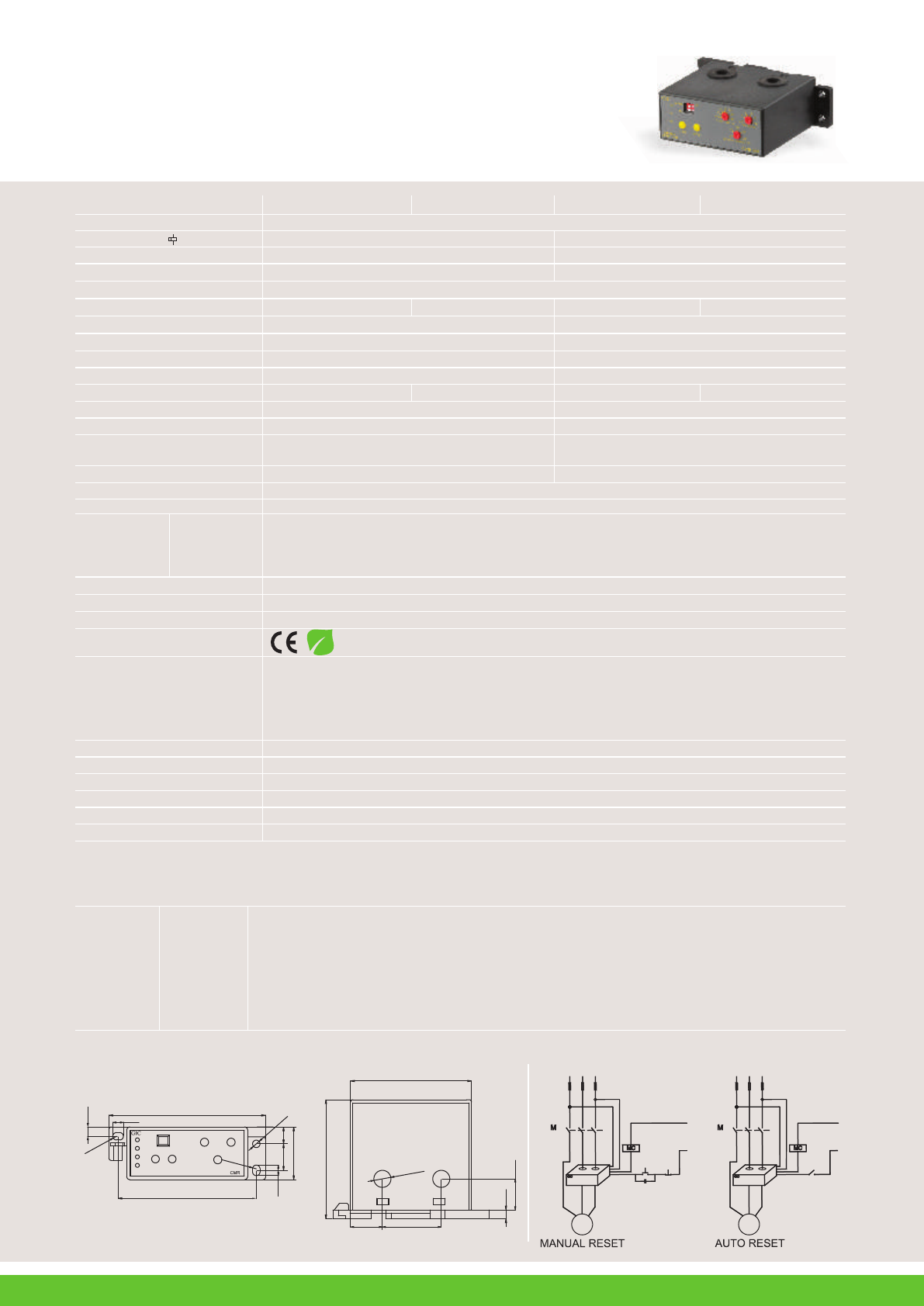
- PTC Thermistor Relay & 63
- Phase Sequence Series PD 225 63
- 17A122CB0 64
- 17B122AA0 64
- 17C112EB0 17D112DA0 64
- 17G544FF1 17G514FF1 65
- 17G644FF1 17G614FF1 65
- REMOTE TEST / RESET 66
- FAIL- SAFE LATCH 66
- 17G715GF2 17G745GF2 67
- 17G715KF2 17G745KF2 67
- Base / Din Rail Mounting 68
- DIN RAIL 35mm 68
- TEMPERATURE CONTROLLERS 69
- 151B12B 151C12B 70
- 151D13B1 71
- 151A13B1 71
- 151B13B1 151C13B1 71
- 74
© 2020, manymanuals.com. All rights reserved. | 0.027 s |
 Manymanuals.com
 Manymanuals.de
 Manymanuals.fr
 Manymanuals.it
 Manymanuals.pl
 Manymanuals.cz
 Manymanuals.es
 Manymanuals-pt.com
Comments to this Manuals