Delta 36-841 User Manual Page 27
- Page / 40
- Table of contents
- BOOKMARKS
- INSTRUCTION MANUAL 1
- GENERAL SAFETY RULES 2
- SAVE THESE INSTRUCTIONS 3
- Refer to them often 3
- POWER CONNECTIONS 4
- MOTOR SPECIFICATIONS 4
- GROUNDING INSTRUCTIONS 4
- OPERATING INSTRUCTIONS 5
- 52" UNIFENCE 7
- INSTRUCTIONS 8
- /4" hex head screws 9
- ASSEMBLING BLADE 10
- GUARD AND SPLITTER 10
- ASSEMBLY 10
- FASTENING MOTOR CORD 12
- TO SAW FRAME 12
- Removing the motor cover 13
- Attaching the motor cover 13
- GUIDE RAIL TO TABLE 16
- SHELF BOARD 16
- ASSEMBLING UNIFENCE 16
- RAIL STOP 18
- SETTING FLIP STOP 18
- ASSEMBLING FENCE TO 20
- UNIFENCE BODY 20
- FENCE OPERATION 20
- RIPPING WITH THE 21
- UNIFENCE 21
- ADJUSTING FENCE PARALLEL 22
- TO MITER GAGE SLOTS 22
- ADJUSTING FENCE 90 22
- DEGREES TO TABLE 22
- ADJUSTING CLAMPING 23
- ACTION OF FENCE 23
- LOCKING HANDLE 23
- RIPPING ON LEFT SIDE OF 23
- SAW BLADE 23
- USING THE FENCE AS A 24
- CUT-OFF GAGE 24
- USING AUXILIARY WOOD 24
- FACING ON THE UNIFENCE 24
- ASSEMBLING GUIDE RAILS 25
- ASSEMBLING TABLE LEGS 26
- TO EXTENSION TABLE 26
- ASSEMBLING EXTENSION TABLE 26
- TO FRONT AND REAR RAILS 26
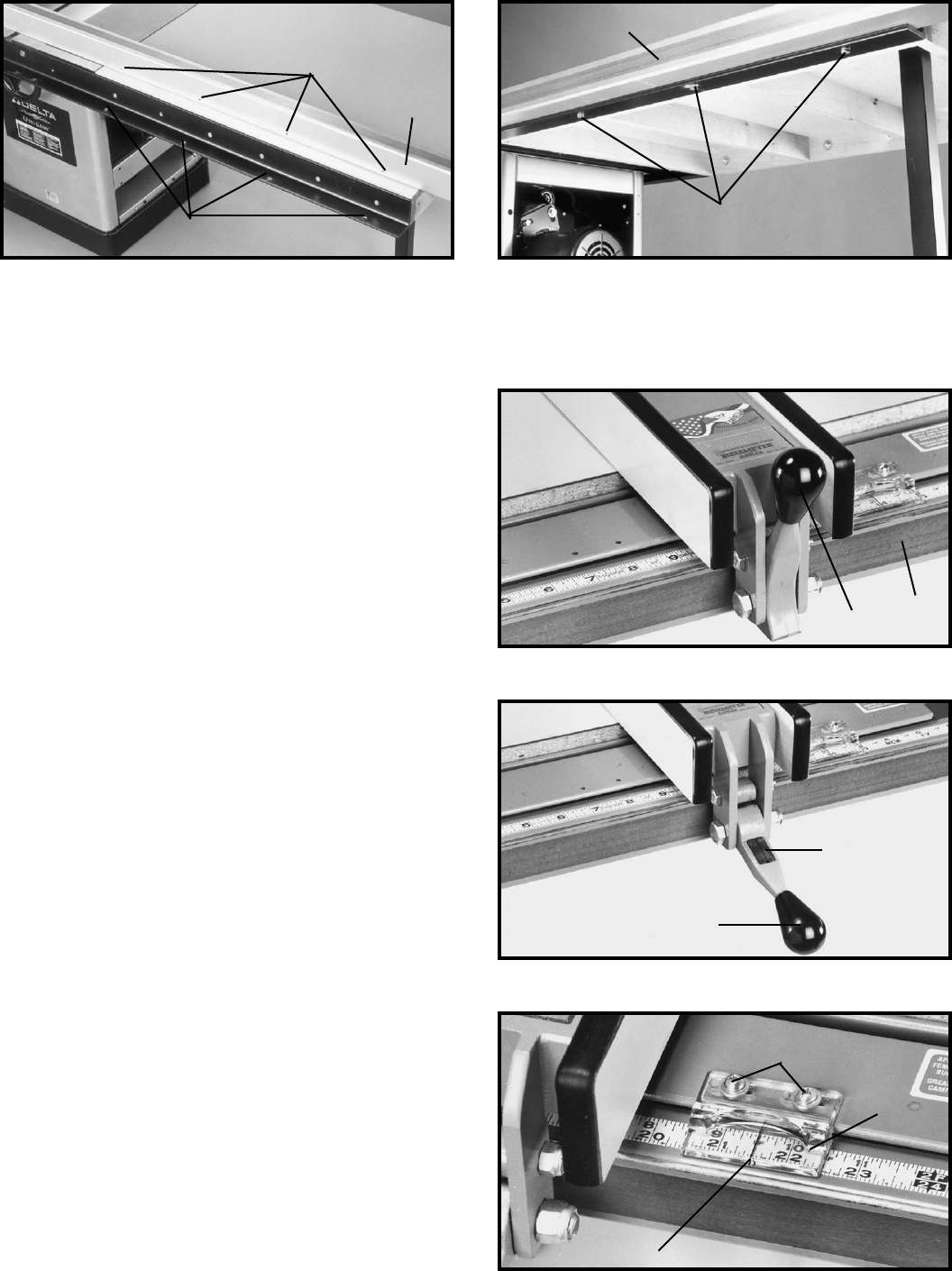
- ASSEMBLING GUIDE TUBE 27
- TO FRONT RAIL 27
- OPERATING CONTROLS 29
- AND UNISAW ADJUSTMENTS 29
- ADJUSTING 90 AND 45 30
- DEGREE POSITIVE STOPS 30
- ADJUSTING TABLE 30
- ADJUSTING TABLE INSERT 31
- MITER GAGE OPERATION 31
- AND ADJUSTMENT 31
- MAINTENANCE 32
- OPERATIONS 33
- FACING ON BIESEMEYER 34
- RIP FENCE 34
- USING ACCESSORY 35
- MOULDING CUTTERHEAD 35
- DADO HEAD 36
- BLADE GUARD ACCESSORIES 37
- PUSH STICK 38
- Two Year Limited Warranty 39
- • DELTA SERVICE CENTERS 40
- • DELTA) 40
Related products and manuals for Power saws Delta 36-841
 (28 pages)
(1 pages)
(1 pages)
(28 pages)
(1 pages)
(1 pages)
© 2020, manymanuals.com. All rights reserved. | 2.964 s |
 Manymanuals.com
 Manymanuals.de
 Manymanuals.fr
 Manymanuals.it
 Manymanuals.pl
 Manymanuals.cz
 Manymanuals.es
 Manymanuals-pt.com
Comments to this Manuals