Delta (Model 31-300) Instruction Manual Page 16
- Page / 60
- Table of contents
- BOOKMARKS
- Instruction Manual 1
- Manuel d’utilisation 1
- Manual de instrucciones 1
- TABLE OF CONTENTS 2
- IMPORTANT SAFETY INSTRUCTIONS 2
- GENERAL SAFETY RULES 3
- SAVE THESE INSTRUCTIONS 4
- POWER CONNECTIONS 5
- MOTOR SPECIFICATIONS 5
- GROUNDING INSTRUCTIONS 5
- EXTENSION CORDS 6
- FUNCTIONAL DESCRIPTION 7
- CARTON CONTENTS 7
- ASSEMBLY 8
- ASSEMBLING THE STAND 9
- ATTACHING THE SANDING DISC 10
- ATTACHING THE DISC TABLE 11
- ATTACHING THE BELT TABLE 11
- OPERATION 12
- TO THE BELT 13
- TILTING THE BELT SANDER TABLE 14
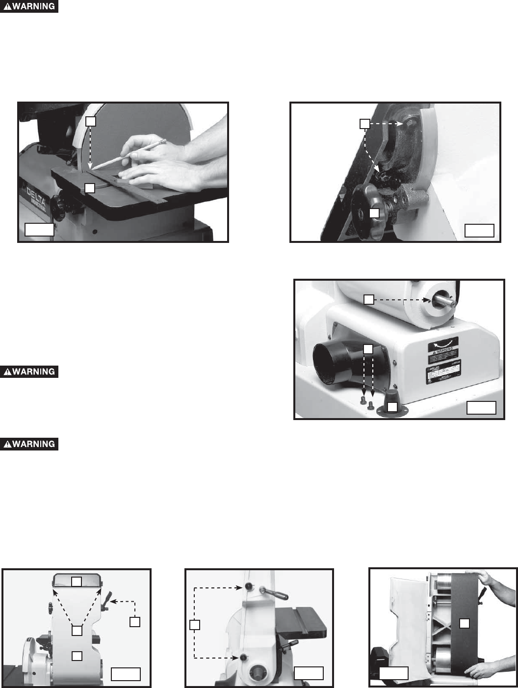
- POWER TAKE-OFF SHAFT 16
- REPLACING THE SANDING BELT 16
- MACHINE USE 17
- TROUBLESHOOTING 18
- MAINTENANCE 18
- REPLACEMENT PARTS 19
- SERVICE AND REPAIRS 19
- WARRANTY 20
- ACCESSORIES 20
- CONSERVEZ CES INSTRUCTIONS! 21
- RÈGLES DE SÉCURITÉ GÉNÉRALES 22
- CONSERVER CES DIRECTIVES 23
- RACCORDEMENTS ÉLECTRIQUES 24
- SPÉCIFICATIONS DU MOTEUR 24
- CORDON DE RALLONGE 25
- DESCRIPTION FONCTIONNELLE 26
- CONTENUS DE BOITE 26
- ASSEMBLAGE 27
- ASSEMBLAGE DU SOCLE 28
- FIXATION DU MOTEUR AU SOCLE 28
- FIXATION DU DISQUE ABRASIF 29
- FONCTIONNEMENT 31
- ABRASIVE 32
- AVEC LA BANDE ABRASIVE 33
- ARBRE DE PRISE DE FORCE 35
- ENTRETIEN 37
- DEPANNAGE 37
- PIÈCES DE RECHANGE 38
- ENTRETIEN ET RÉPARATION 38
- ACCESSOIRIES 39
- GARANTIE 39
- Proposición de CALIFORNIA 65 40
- NORMAS GENERALES DE SEGURIDAD 41
- GUARDE ESTAS INSTRUCCIONES 42
- ESPECIFICACIONES DEL MOTOR 43
- CORDONES DE EXTENSIÓN 44
- DESCRIPCIÓN FUNCIONAL 45
- CONTENIDO DE CARTON 45
- ENSAMBLAJE 46
- MONTAJE DE LA BASE 47
- ACOPLE DEL MOTOR A LA BASE 47
- COLOCACIÓN DEL DISCO DE LIJAR 48
- ACOPLE DEL BANCO PARA DISCO 49
- ACOPLE DEL BANCO PARA BANDA 49
- OPERACIÓN 50
- EJE DESMONTABLE ELÉCTRICO 54
- UTILIZAR LA MAQUINA 55
- MANTENIMIENTO 56
- LOCALIZACION DE FALLAS 56
- SERVICIO 57
- GARANTIA 58
- ACCESORIOS 58
- Delta Machinery 60
- 4825 Highway 45 North 60
- Jackson, TN 38305 60
- (800) 223-7278 60
Related products and manuals for Power sanders Delta (Model 31-300)
 (100 pages)


 (32 pages)
 (23 pages)
 (82 pages)
(1 pages)
(21 pages)
(10 pages)
(82 pages)
(1 pages)
(21 pages)
(10 pages)
© 2020, manymanuals.com. All rights reserved. | 1.008 s |
 Manymanuals.com
 Manymanuals.de
 Manymanuals.fr
 Manymanuals.it
 Manymanuals.pl
 Manymanuals.cz
 Manymanuals.es
 Manymanuals-pt.com
Comments to this Manuals