Delta 36-714 User Manual Page 15
- Page / 80
- Table of contents
- BOOKMARKS
- Instruction Manual 1
- Manuel d’Utilisation 1
- Manual de Instrucciones 1
- TABLE OF CONTENTS 2
- IMPORTANT SAFETY INSTRUCTIONS 2
- GENERAL SAFETY RULES 3
- POWER CONNECTIONS 5
- MOTOR SPECIFICATIONS 5
- GROUNDING INSTRUCTIONS 5
- EXTENSION CORDS 6
- FUNCTIONAL DESCRIPTION 7
- CARTON CONTENTS 7
- ASSEMBLY 8
- INSTALLING THE DRIVE BELT 9
- EXTENSION WINGS 10
- INSTALLING THE SWITCH 10
- ROUTING THE CORD 11
- ATTACHING A SAW BLADE 13
- INSTALLING TABLE INSERT 13
- ADJUSTING TABLE INSERT 14
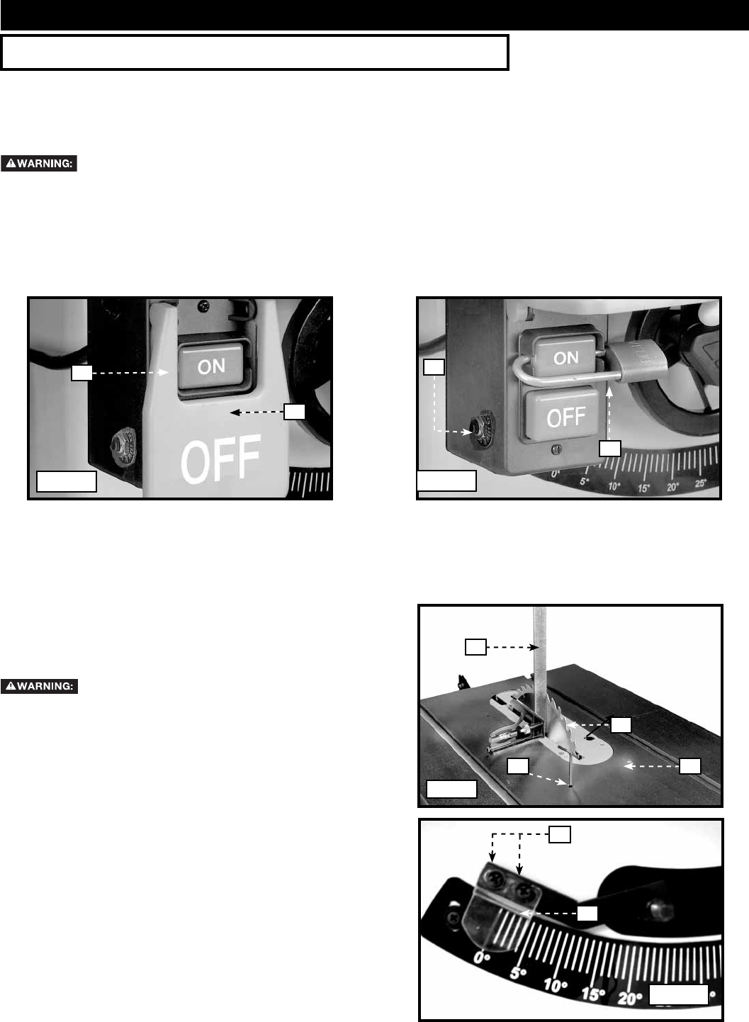
- OPERATION 15
- ADJUSTING BLADE ALIGNMENT 16
- MACHINE USE 17
- BLADE GUARD AND SPLITTER USE 18
- CROSS-CUTTING 18
- MITERING 19
- BEVEL RIPPING 21
- PUSH STICK 24
- TROUBLESHOOTING 25
- MAINTENANCE 25
- WARRANTY 26
- ACCESSORIES 26
- CONSERVEZ CES INSTRUCTIONS! 27
- RÈGLES DE SÉCURITÉ GÉNÉRALES 28
- CONSERVER CES DIRECTIVES 29
- RACCORDEMENTS ÉLECTRIQUES 30
- SPÉCIFICATIONS DU MOTEUR 30
- CORDON DE RALLONGE 31
- DESCRIPTION FONCTIONNELLE 32
- CONTENUS DE BOITE 32
- ASSEMBLAGE 33
- RALLONGES 35
- ACHEMINEMENT DU CORDON 36
- INSTALLATION DES PORTE-OUTILS 39
- FONCTIONNEMENT 40
- UTILISATION DE LA MACHINE 42
- TRONÇONNAGE 43
- DÉCOUPE À L’ONGLET 44
- TRONÇONNAGE EN BISEAU 44
- DÉCOUPE À ONGLET MIXTE 44
- SCIAGE EN LONG 44
- SCIAGE SUR LE LONG EN BISEAU 46
- Fig. 67 49
- Fig. 68 49
- POUSSOIR 50
- DEPANNAGE 51
- ENTRETIEN 51
- ACCESSOIRIES 52
- GARANTIE 52
- Proposición de CALIFORNIA 65 53
- NORMAS GENERALES DE SEGURIDAD 54
- ESPECIFICACIONES DEL MOTOR 56
- CORDONES DE EXTENSIÓN 57
- DESCRIPCIÓN FUNCIONAL 58
- CONTENIDO DE CARTON 58
- ENSAMBLAJE 59
- BASES DE EXTENSIÓN 61
- INSTALACIÓN DEL INTERRUPTOR 61
- RECORRIDO DEL CABLE 62
- ACOPLE DE HOJA 64
- AJUSTE DEL INSERTO DE MESA 65
- OPERACIÓN 66
- UTILIZAR LA MAQUINA 68
- CORTE TRANSVERSAL 69
- CORTE A INGLETE 70
- CORTE TRANSVERSAL CON BISEL 70
- CORTE LONGITUDINAL 70
- CORTE LONGITUDINAL CON BISEL 72
- Fig. 67 75
- VARA PARA EMPUJAR 76
- LOCALIZACION DE FALLAS 77
- MANTENIMIENTO 77
- SERVICIO 77
- GARANTIA 78
- ACCESORIOS 78
- Delta Machinery 80
- 4825 Highway 45 North 80
- Jackson, TN 38305 80
- (800) 223-7278 80
Related products and manuals for Power saws Delta 36-714
 (40 pages)
(28 pages)
(1 pages)
(1 pages)
(40 pages)
(28 pages)
(1 pages)
(1 pages)
© 2020, manymanuals.com. All rights reserved. | 0.206 s |
 Manymanuals.com
 Manymanuals.de
 Manymanuals.fr
 Manymanuals.it
 Manymanuals.pl
 Manymanuals.cz
 Manymanuals.es
 Manymanuals-pt.com
Comments to this Manuals