Delta 50-764 User Manual Page 10
- Page / 48
- Table of contents
- BOOKMARKS
- Instruction Manual 1
- Manuel d’Utilisation 1
- Manual de Instrucciones 1
- TABLE OF CONTENTS 2
- IMPORTANT SAFETY INSTRUCTIONS 2
- TOOL WARNING LABEL 3
- GENERAL SAFETY RULES 4
- SAVE THESE INSTRUCTIONS 5
- FUNCTIONAL DESCRIPTION 6
- CARTON CONTENTS 7
- ASSEMBLY 8
- LEGS TO MOTOR/BLOWER 9
- ATTACHING STAND TO LEGS ON 9
- MOTOR/BLOWER ASSEMBLY 9
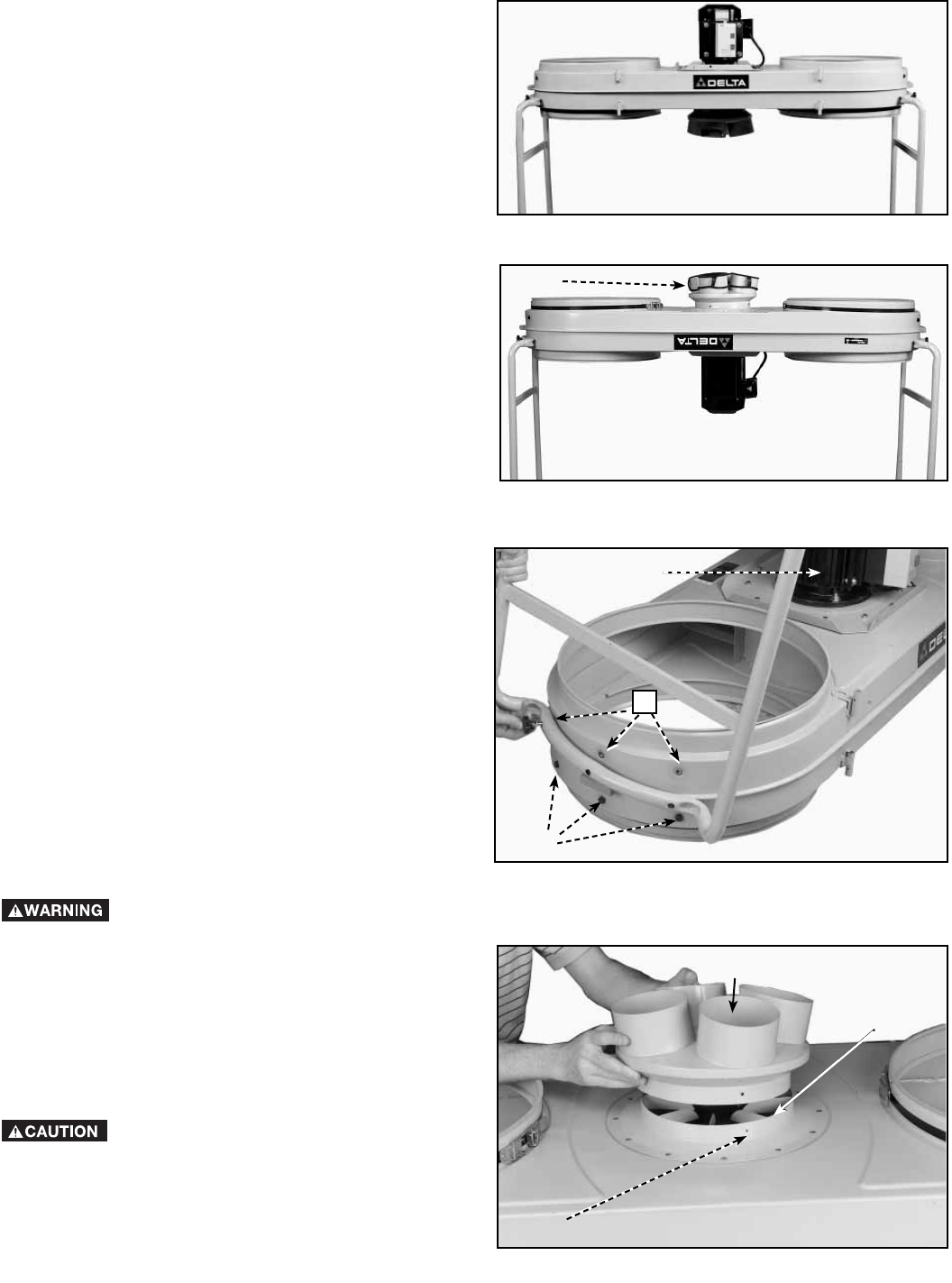
- ALTERNATE SETUP 10
- ATTACHING DUST INTAKE PORTS 10
- ATTACHING DUST COLLECTION BAG 11
- ATTACHING TOP FILTER BAGS 12
- SINGLE AND THREE PHASE WIRING 13
- ATTACHING ACCESSORY HOSE 13
- TO INTAKE PORT 13
- OPERATION 14
- TROUBLESHOOTING GUIDE 15
- MAINTENANCE 15
- ACCESSORIES 16
- WARRANTY 16
- FRANÇAIS 17
- CONSERVEZ CES INSTRUCTIONS! 18
- RÈGLES DE SÉCURITÉ GÉNÉRALES 19
- CONSERVER CES DIRECTIVES 20
- DESCRIPTION FONCTIONNELLE 21
- CONTENUS DE BOITE 21
- DÉSEMBALLAGE ET NETTOYAGE 22
- ASSEMBLAGE 23
- ASSEMBLAGE ALTERNATIF 24
- ASSEMBLAGE DES GOULOTTES À 24
- POUSSIÈRE 24
- POUSSIÈRES 25
- FIXATION DES SACS FILTRANTS 26
- SUPÉRIEURS 26
- RACCORD DU TUYAU ACCESSOIRE 27
- À L’ORIFICE D’ADMISSION 27
- CÂBLAGE DE MOTEURS TRIPHASÉS 27
- OU MONOPHASÉS 27
- FONCTIONNEMENT 28
- DEPANNAGE 29
- ENTRETIEN 29
- ACCESSOIRIES 30
- GARANTIE 30
- PROPOSICIÓN DE CALIFORNIA 65 32
- NORMAS GENERALES DE SEGURIDAD 33
- GUARDE ESTAS INSTRUCCIONES 34
- DESCRIPCIÓN FUNCIONAL 35
- CONTENIDO DE CARTON 36
- ENSAMBLAJE 37
- INSTALACIÓN ALTERNATIVA 39
- CÓMO CONECTAR LOS ORIFICIOS 39
- DE ADMISIÓN DE POLVO 39
- CÓMO CONECTAR LA BOLSA DE 40
- RECOLECCIÓN DE POLVO 40
- CÓMO CONECTAR LAS BOLSAS DE 41
- FILTRO SUPERIORES 41
- CÓMO CONECTAR LA MANGUERA 42
- CABLEADO DE UNA Y TRES FASES 42
- OPERACIÓN 43
- MANTENIMIENTO 44
- LOCALIZACION DE FALLAS 44
- SERVICIO 44
- GARANTIA 45
- ACCESORIOS 45
© 2020, manymanuals.com. All rights reserved. | 3.163 s |
 Manymanuals.com
 Manymanuals.de
 Manymanuals.fr
 Manymanuals.it
 Manymanuals.pl
 Manymanuals.cz
 Manymanuals.es
 Manymanuals-pt.com
Comments to this Manuals