Delta TP400LS Instruction Manual Page 8
- Page / 21
- Table of contents
- BOOKMARKS
- 12½" Portable Planer 1
- GENERAL SAFETY RULES 2
- SAVE THESE INSTRUCTIONS 4
- Refer to them often 4
- POWER CONNECTIONS 5
- MOTOR SPECIFICATIONS 5
- GROUNDING INSTRUCTIONS 5
- EXTENSION CORDS 6
- FUNCTIONAL DESCRIPTION 7
- UNPACKING AND CLEANING 7
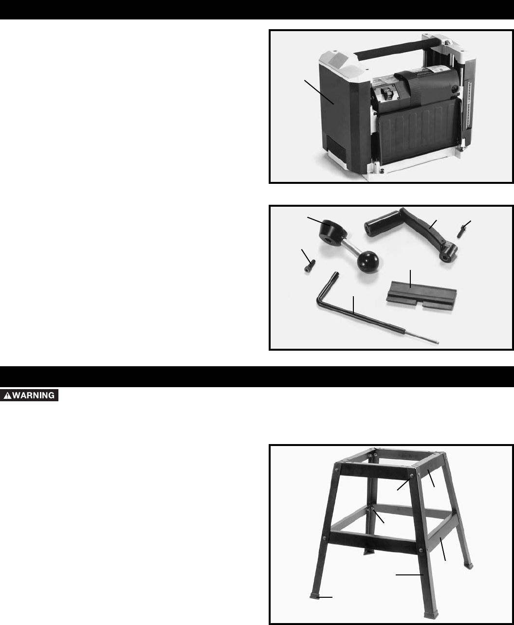
- PLANER PARTS 8
- ASSEMBLY 8
- FASTENING PLANER TO STAND 10
- RECOMMENDED 12
- DEPTH OF CUT 12
- LEVELING 12
- TABLE EXTENSIONS 12
- KNIFE TRANSFER TOOL 13
- WRENCH STORAGE 13
- REPLACING KNIVES 14
- ADJUSTING HEIGHT 16
- OF OUTFEED ROLLER 16
- OPERATION 17
- MAINTENANCE 18
- BRUSH INSPECTION 18
- AND REPLACEMENT 18
- LUBRICATION 18
- ACCESSORIES 20
- • DELTA SERVICE CENTERS 21
- • DELTA) 21
Related products and manuals for Power planers Delta TP400LS


 (72 pages)
© 2020, manymanuals.com. All rights reserved. | 1.515 s |
 Manymanuals.com
 Manymanuals.de
 Manymanuals.fr
 Manymanuals.it
 Manymanuals.pl
 Manymanuals.cz
 Manymanuals.es
 Manymanuals-pt.com
Comments to this Manuals