Delta 36-550 Instruction Manual Page 12
- Page / 24
- Table of contents
- BOOKMARKS
- 10" Table Saw 1
- GENERAL SAFETY RULES 2
- SAVE THESE INSTRUCTIONS 3
- Refer to them often 3
- POWER CONNECTIONS 4
- MOTOR SPECIFICATIONS 4
- GROUNDING INSTRUCTIONS 4
- OPERATING INSTRUCTIONS 5
- FOR MODEL 36-560 ONLY 7
- ASSEMBLY 8
- BLADE GUARD AND 9
- SPLITTER ASSEMBLY 9
- ASSEMBLING EXTENSION WING 11
- ASSEMBLING GUIDE RAIL TO SAW 11
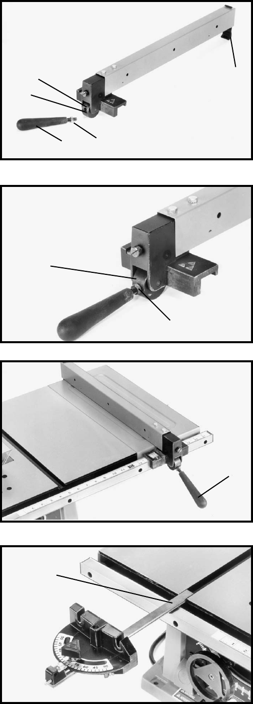
- ASSEMBLING RIP FENCE 12
- MITER GAGE 12
- ASSEMBLING 13
- MITER GAGE HOLDER 13
- OUTFEED SUPPORT 14
- 5/16" HOLES 15
- SAW PLACEMENT 15
- BLADE TILTING CONTROL 17
- RIP FENCE OPERATION 18
- AND ADJUSTMENTS 18
- ADJUSTING BLADE 19
- PARALLEL TO 19
- MITER GAGE SLOTS 19
- CHANGING THE BLADE 19
- OPERATION 20
- USING AUXILIARY WOOD 21
- FACING ON RIP FENCE 21
- CONSTRUCTING A FEATHERBOARD 22
- PUSH STICK 23
- Two Year Limited Warranty 24
Related products and manuals for Power tools Delta 36-550
 (16 pages)
(20 pages)
(23 pages)
(13 pages)
(28 pages)
(40 pages)
(21 pages)
(10 pages)
(16 pages)
(16 pages)
(20 pages)
(23 pages)
(13 pages)
(28 pages)
(40 pages)
(21 pages)
(10 pages)
(16 pages)

 (76 pages)
(167 pages)
(17 pages)
(40 pages)
(16 pages)
(8 pages)
(76 pages)
(167 pages)
(17 pages)
(40 pages)
(16 pages)
(8 pages)
 (44 pages)
(64 pages)
(64 pages)
(44 pages)
(64 pages)
(64 pages)
© 2020, manymanuals.com. All rights reserved. | 1.931 s |
 Manymanuals.com
 Manymanuals.de
 Manymanuals.fr
 Manymanuals.it
 Manymanuals.pl
 Manymanuals.cz
 Manymanuals.es
 Manymanuals-pt.com
Comments to this Manuals