Delta RMC151 User Manual Page 32
- Page / 44
- Table of contents
- BOOKMARKS
- STARTUP 1
- Where to Get Help 2
- Contents 3
- Step 1: Mounting 4
- Step 2: Wiring 5
- Step 3: Install RMCTools 6
- Step 4: Connect RMC to PC 7
- Step 5: Start a New Project 8
- Project Pane 10
- Saving Settings 11
- 1. Save RMCTools Project 11
- 2. Update Flash 11
- 3. Repeat Often 11
- Step 6: Define the Axes 12
- View Axis Definitions 13
- Edit Axis Definitions 13
- Step 7: Test an Actuator 14
- Configure Feedback 17
- SSI Feedback 18
- Analog Feedback 19
- Quadrature Encoder Feedback 19
- Resolver Feedback 19
- Verify Feedback 20
- Step 9: Scale and Offset 21
- Enable the Axes 22
- Step 11: Tuning 23
- Commands 25
- User Programs 25
- Communications 26
- Discrete I/O 26
- Variables 26
- Program Triggers 26
- Diagnostic Tools 27
- Appendix A: Wiring 28
- General Wiring Information 29
- Wiring Power 30
- UL and CUL Requirements 30
- Power Wiring Diagram 30
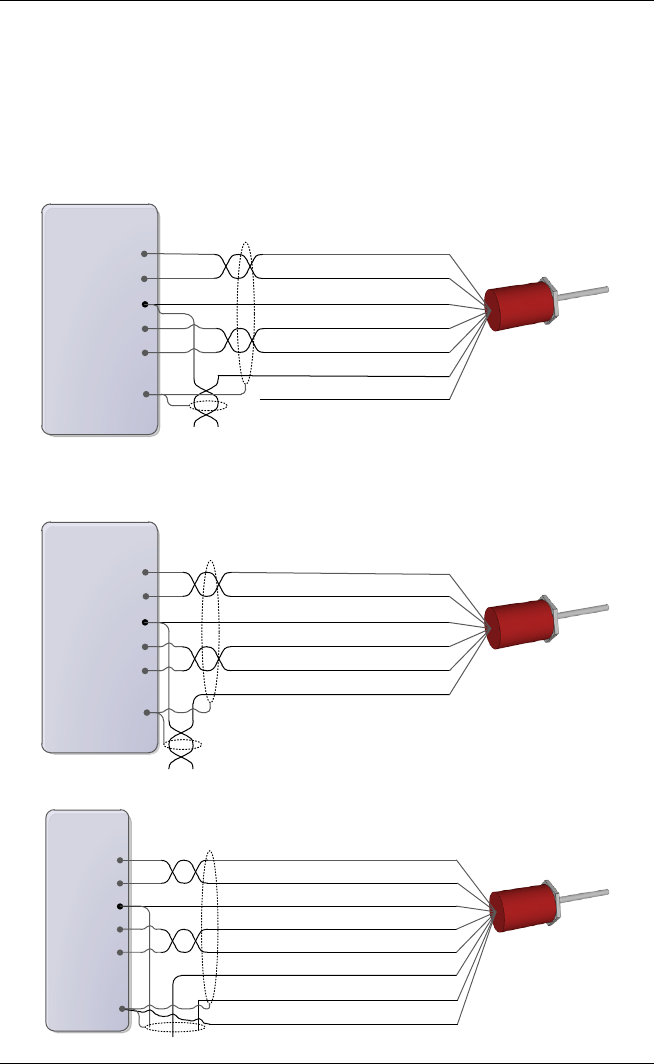
- 6-pin MDT 31
- Connector 31
- Power Supply 31
- SSI Transducer Wiring 33
- Voltage Transducer, 3-Wire 35
- Analog 4-20 mA 36
- Quadrature Encoder Wiring 37
- 8-pin Resolver 38
- Discrete Output Wiring 39
- DI/O and UI/O Module 39
- RMC150E Module 39
- Discrete Input Wiring 40
- UL and CUL 42
- Class I Div 2 42
Related products and manuals for Sensors Delta RMC151
 (68 pages)
(951 pages)
(9 pages)
(34 pages)
(4 pages)
(22 pages)
(150 pages)
(105 pages)
(68 pages)
(951 pages)
(9 pages)
(34 pages)
(4 pages)
(22 pages)
(150 pages)
(105 pages)
© 2020, manymanuals.com. All rights reserved. | 1.080 s |
 Manymanuals.com
 Manymanuals.de
 Manymanuals.fr
 Manymanuals.it
 Manymanuals.pl
 Manymanuals.cz
 Manymanuals.es
 Manymanuals-pt.com
Comments to this Manuals