Delta 43-355 Instruction Manual
Browse online or download Instruction Manual for Power tools Delta 43-355. Delta 43-355 Instruction manual User Manual
- Page / 16
- Table of contents
- BOOKMARKS
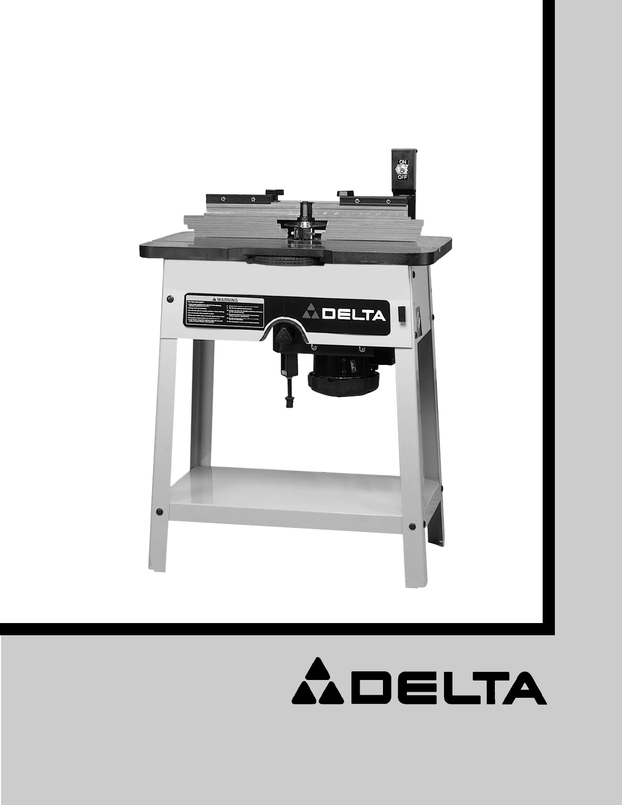
- Wood Shaper 1
- GENERAL SAFETY RULES 2
- SAVE THESE INSTRUCTIONS 3
- POWER CONNECTIONS 4
- MOTOR SPECIFICATIONS 4
- GROUNDING INSTRUCTIONS 4
- MINIMUM GAUGE EXTENSION CORD 5
- ASSEMBLY INSTRUCTIONS 6
- ASSEMBLING 7
- SWITCH ARM 7
- CHANGING POSITION OF 10
- THE SWITCH ARM 10
- REVERSING 10
- SPINDLE ROTATION 10
- OVERLOAD PROTECTION 10
- FENCE ADJUSTMENTS 11
- CHANGING SPEEDS AND 11
- ADJUSTING BELT TENSION 11
- CHANGING SPINDLES 12
- AND REPLACING BELTS 12
- OPERATION 13
- SHAPING WITH COLLARS 14
- AND STARTING PIN 14
- POSITION OF COLLARS 14
- ACCESSORIES 15
- • DELTA SERVICE CENTERS 16
- • DELTA) 16
Summary of Contents
INSTRUCTION MANUAL2 SpeedWood Shaper(Model 43-355)PART NO. 432-09-651-0004 (01/11/02)Copyright © 2002 Delta MachineryTo learn more about DELTA MACHINE
10Fig. 21Fig. 22Fig. 23Fig. 24CHANGING POSITION OFTHE SWITCH ARMThe switch arm (A) can be positioned in the verticalposition, as shown in Fig. 21 , or
11FENCE ADJUSTMENTSIMPORTANT: The individual fence segments (A) shouldbe adjusted endwise so the opening is never more thanrequired to clear the spind
12Fig. 28 Fig. 29Fig. 30Fig. 31Fig. 33Fig. 32CHANGING SPINDLESAND REPLACING BELTSCHANGING SPINDLESThe spindle assembly in your shaper is equipped with
13Fig. 34Fig. 35CHECKING AND ALIGNINGMOTOR PULLEY TOSPINDLE1. DISCONNECT MACHINE FROM POWER SOURCE.2. Lift up latch (A) Fig. 34, pull out and lower fr
14SHAPING WITH COLLARSAND STARTING PINWhen shaping with collars and starting pin, the followingrules must always be followed for good work and safetyi
15STARTING PIN1. Your machine is supplied with a tapered starting pinwhich is used as a support when starting the cut. Thestart-ing pin is placed in o
The following are trademarks of PORTER-CABLE·DELTA (Las siguientes son marcas registradas de PORTER-CABLE S.A.): BAMMER®,INNOVATION THAT WORKS®, JETST
2GENERAL SAFETY RULESWoodworking can be dangerous if safe and proper operating procedures are not followed. As with all machinery, thereare certain ha
31. DO NOT OPERATE THIS MACHINE UNTIL it isassembled and installed according to the instructions.2. OBTAIN ADVICE from your supervisor, instructor, or
4POWER CONNECTIONSA separate electrical circuit should be used for your machines. This circuit should not be less than #12 wire and shouldbe protected
Use proper extension cords. Make sure your extension cord is in good condition and is a 3-wire extension cord whichhas a 3-prong grounding type plug a
6UNPACKINGThe shaper is shipped with the motor assembly, spindleand belt assembled to the underside of the table.Place the shaper table and motor asse
7Fig. 6Fig. 8Fig. 7Fig. 9Fig. 104. Assemble 3/8" rubber grommet (Z) Fig. 6, to roundhole (A) in leg.5. Assemble front panel (B) Fig. 7, to the ou
8ASSEMBLING FENCETO SHAPER TABLEPlace the fence assembly (A) Fig. 11, on the shaper tableand fasten it to the table using the two long threadedlocking
9FASTENING SHAPER TOSUPPORTING SURFACEIF DURING OPERATION THERE IS ANY TENDENCYFOR THE SHAPER TO TIP OVER, SLIDE OR WALKON THE SUPPORTING SURFACE, THE
Related products and manuals for Power tools Delta 43-355


 (56 pages)
(16 pages)
(28 pages)
(27 pages)
(16 pages)
(52 pages)
(48 pages)
(28 pages)
(48 pages)
(21 pages)
(15 pages)
(84 pages)
(16 pages)
(18 pages)
(22 pages)
(16 pages)
(24 pages)
(18 pages)
(14 pages)
(17 pages)
(56 pages)
(16 pages)
(28 pages)
(27 pages)
(16 pages)
(52 pages)
(48 pages)
(28 pages)
(48 pages)
(21 pages)
(15 pages)
(84 pages)
(16 pages)
(18 pages)
(22 pages)
(16 pages)
(24 pages)
(18 pages)
(14 pages)
(17 pages)
© 2020, manymanuals.com. All rights reserved. | 0.417 s |
 Manymanuals.com
 Manymanuals.de
 Manymanuals.fr
 Manymanuals.it
 Manymanuals.pl
 Manymanuals.cz
 Manymanuals.es
 Manymanuals-pt.com
Comments to this Manuals