Delta 18-900L Use and Care Manual Page 14
- Page / 68
- Table of contents
- BOOKMARKS
- WiTH lAsers 1
- TABLE OF CONTENTS 2
- IMPORTANT SAFETY INSTRUCTIONS 2
- GENERAL SAFETY RULES 3
- SAVE THESE INSTRUCTIONS 4
- POWER CONNECTIONS 5
- MOTOR SPECIFICATIONS 5
- GROUNDING INSTRUCTIONS 5
- FUNCTIONAL DESCRIPTION 6
- CARTON CONTENTS 7
- ASSEMBLING DRILL PRESS PARTS 9
- ASSEMBLING HEADSTOCK 10
- TO COLUMN AND BASE 10
- INSTALLING THE CHUCK 10
- ATTACHING THE 11
- LED WORK LIGHT 11
- CHUCK KEY STORAGE 11
- TABLE INSERT 12
- TABLE LOCKING WRENCH STORAGE 12
- BELT TENSION LEVER HANDLE 12
- OPERATION 13
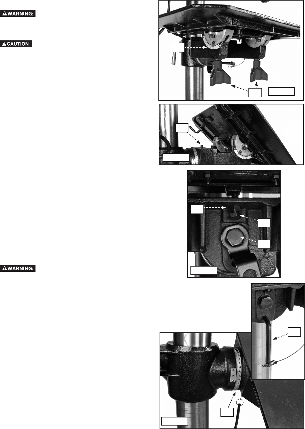
- TABLE ADJUSTMENTS 14
- ADJUSTING THE SPINDLE RETURN 15
- CHECKING LASER ADJUSTMENT 16
- SPINDLE SPEEDS 17
- DRILLING HOLES TO DEPTH 18
- MACHINE USE 19
- CORRECT DRILLING SPEEDS 20
- DRILLING WOOD 20
- DRILLING METAL 20
- TROUBLESHOOTING 21
- MAINTENANCE 21
- ACCESSORIES 22
- WARRANTY 22
- RÈGLES DE SÉCURITÉ GÉNÉRALES 24
- CONSERVER CES DIRECTIVES 25
- Ouvertures laser 26
- RACCORDEMENTS ÉLECTRIQUES 27
- SPÉCIFICATIONS DU MOTEUR 27
- DESCRIPTION FONCTIONNELLE 28
- CONTENUS DE BOITE 29
- 24" (610 mm) MINIMUM 30
- ASSEMBLAGE DE LA PERCEUSE À 31
- LA COLONNE ET LA BASE 32
- INSTALLATION DU MANDRIN 32
- PLAQUETTE 34
- FONCTIONNEMENT 35
- RÉGLAGES DE LA TABLE 36
- ÉLEVER ET ABAISSER LA BROCHE 37
- VÉRIFICATION DU RÉGLAGE LASER 38
- ACCESSOIRE 39
- MATÉRIAU 39
- LA TENSION DE COURROIE 40
- UTILISATION DE LA MACHINE 41
- RETRAIT DU MANDRIN ET DE 42
- L’ADAPTATEUR DE BROCHE 42
- VITESSES ADÉQUATES DE PERÇAGE 42
- PERÇAGE DU BOIS 42
- PERÇAGE DU MÉTAL 42
- ENTRETIEN 43
- DEPANNAGE 43
- ACCESSOIRIES 44
- GARANTIE 44
- NORMAS GENERALES DE SEGURIDAD 46
- GUARDE ESTAS INSTRUCCIONES 47
- ESPECIFICACIONES DEL LÁSER 48
- ESPECIFICACIONES DEL MOTOR 49
- DESCRIPCIÓN FUNCIONAL 50
- CONTENIDO DE CARTON 51
- 24" (610 mm) MÍNIMO 52
- PRENSA DE TALADRO 53
- FIJAR LA MESA 56
- LA CORREA 56
- ENCASTRE PARA LA MESA 56
- OPERACIÓN 57
- AJUSTES A LA MESA 58
- REVISIÓN DEL AJUSTE DEL LÁSER 60
- ACCESSORIO 61
- BROCAS DE PALA 61
- MATERIAL 61
- LA TENSIÓN DE LA CORREA 62
- UTILIZAR LA MAQUINA 63
- MANTENIMIENTO 65
- LOCALIZACION DE FALLAS 65
- SERVICIO 66
- ACCESORIOS 66
- PÓLIZA DE GARANTÍA 67
- GARANTIA 67
- 5530 Airport Road 68
- Anderson, SC 29626 68
- (800) 223-7278 68
© 2020, manymanuals.com. All rights reserved. | 2.119 s |
 Manymanuals.com
 Manymanuals.de
 Manymanuals.fr
 Manymanuals.it
 Manymanuals.pl
 Manymanuals.cz
 Manymanuals.es
 Manymanuals-pt.com
Comments to this Manuals