Delta 36-412 Service Manual
Browse online or download Service Manual for Circular saws Delta 36-412. Delta 36-412 Technical data User Manual
- Page / 76
- Table of contents
- BOOKMARKS
- Power Tools 1
- 1. PRODUCT NAME 5
- 2. MARKETING OBJECTIVE 5
- 3. APPLICATIONS 5
- 4. SELLING POINTS 5
- ••••••••••••••• 8
- 3000 or more 14
- Cut-off-side 21
- Saw blade 21
- Fixed-side workpiece 21
- 9. ADJUSTMENT OF COMPONENTS 27
- 10. PACKING 28
- --- 39 43
- Wiring diagram (C 12FDH) 43
- Holder (B) [4] 46
- Fence (A) 50
- Fence (B) 50
- Work Flow 55
- ELECTRIC TOOL PARTS LIST 56
- --- 2 --- 10 -- 05 57
- --- 3 ---10 -- 05 58
- ALTERNATIVE PARTS--- 4 59
- 10 -- 05 59
- ALTERNATIVE PARTS --- 5 60
- ALTERNATIVE PARTS--- 6 61
- ALTERNATIVE PARTS --- 7 62
- ALTERNATIVE PARTS--- 8 63
- OPTIONAL ACCESSORIES 64
- STANDARD ACCESSORIES 64
- --- 1 0 65
- Printed in Japan 65
- (051005N) 65
Summary of Contents
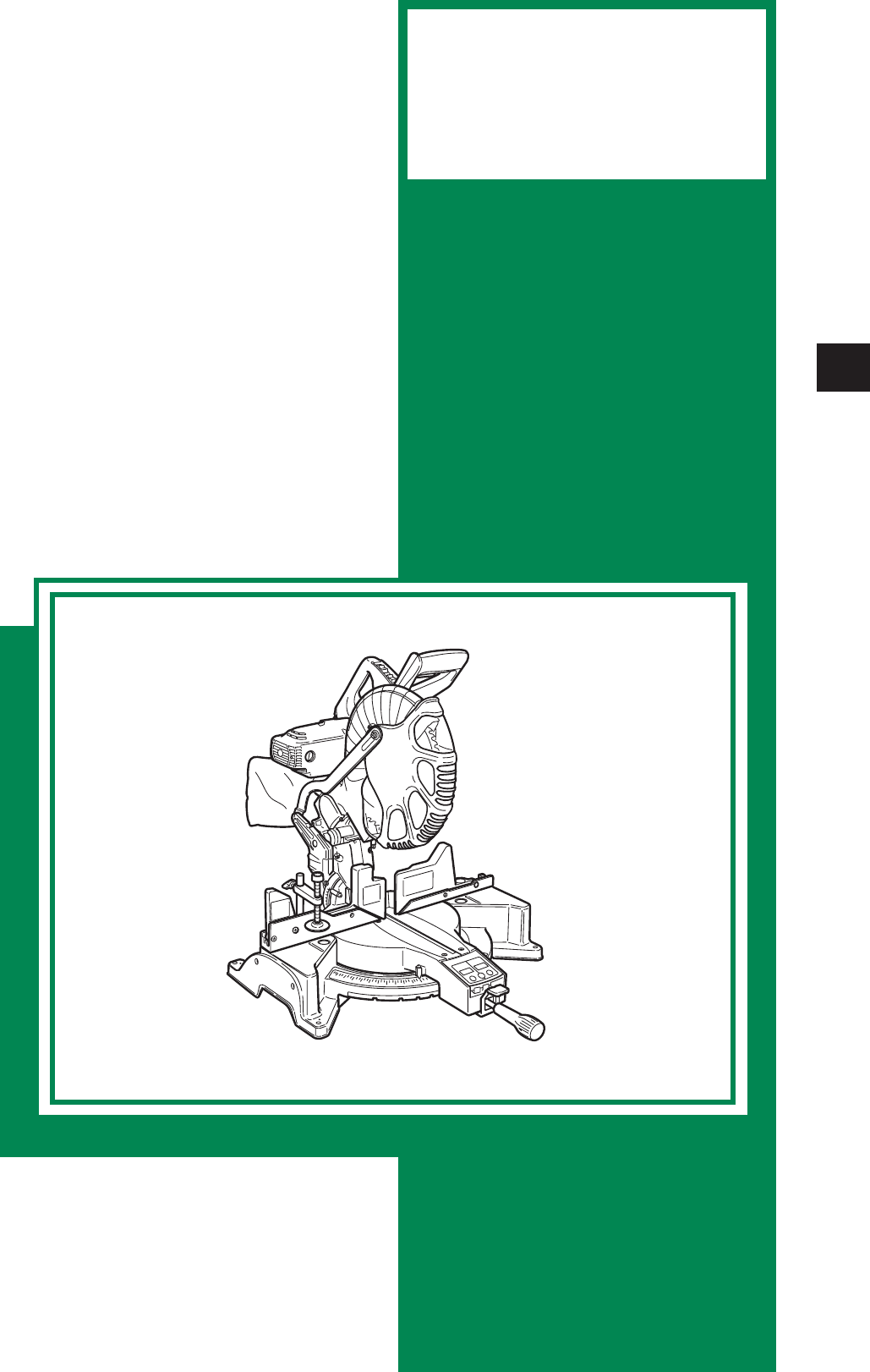
TECHNICAL DATAANDSERVICE MANUALCOMPOUND MITER SAWC 12LDHC 12FDHSPECIFICATIONS AND PARTS ARE SUBJECT TO CHANGE FOR IMPROVEMENTLIST Nos. C 1
--- 6 ---305 (12") (32 teeth)154,0001,5201,950Provided< 1 mWDouble insulationProvided (fixed)305 (12") (60 teeth)154,000ProvidedDouble i
--- 7 ---7. PRECAUTIONS IN SALES PROMOTIONIn the interest of promoting the safest and most efficient use of the Models C 12LDH and C 12FDH CompoundMit
--- 8 ---Fig. 6(4) Caution label (A) (at the front of the hinge) and caution label (C) (at the front of the base)Do not stare into laser beam. If yo
--- 9 ---(7) Warning label (O) (at the front of sub fence (C) (standard accessory))Fig. 107-3. Relative StandardsStandards, regulations and guidelines
--- 10 ---7-5. Ambient Illuminance and Visibility of Laser LineThe visibility of the laser line on the workpiece changes depending on the brightness o
--- 11 ---The Models C 12LDH and C 12 FDH are equipped with the lasermarker for easy alignment with the ink line on the workpiece.Turn on the digital
--- 12 ---CAUTION:Laser radiation - Do not stare into beam.Laser radiation on work table. Do not stare into beam. If your eye is exposed directly to
--- 13 ---8-2. Before Cutting(1) Oblique angleBefore the power tool is shipped from the factory, it is adjusted for 0˚, right angle, left 45˚ bevel cu
--- 14 ---(4) Stopper for precision cutting (Stopper and holder are optional accessory)The stopper facilitates continuous precision cutting in lengths
--- 15 ---8-4. Confirmation for Use of Sub Fence(1) Confirmation for use of sub fence (A)WARNING: In the case of right bevel cutting, turn sub fence (
REMARK:Throughout this TECHNICAL DATA AND SERVICE MANUAL, a symbol(s)is(are) used in the place of company name(s) and model name(s)
--- 16 ---In the case of left bevel angle cutting, remove sub fence (C)by sliding to the side and removing from the top as shown inFig. 21. Loosen kn
--- 17 --- CAUTION:When the workpiece is secured on the left side, the cut-offportion comes to rest on the side of the saw blade as illustratedin
--- 18 ---Type ofcrown moldingTo process crown molding atpositions and in Fig. 24To process crown molding atpositions and in Fig. 24Mi
--- 19 ---(1) Setting to cut crown molding at positions and in Fig. 25 (See Fig. 26; tilt the head to the left.):Turn the turn table to the
--- 20 ---(4) Setting to cut crown moldings at positions and in Fig. 25 (See Fig. 31; tilt the head to the right.):Turn the turn table to th
--- 21 ---Cutting method of crown molding without tilting the saw blade6 mm wing boltCrown molding stopper (L)(Optional accessory)Crown moldingstopper
--- 22 ---Side handleReset button8-6. Digital Display Panel (For Model C 12LDH)(1) Turning on the digital display switch shows 0˚ for bothmiter and be
--- 23 ---9. ADJUSTMENT OF COMPONENTS9-1. Bevel Angle Fine AdjustmentFig. 37-a Fig. 37-b8 mm bolt (C)Knob (A)8 mm bolt (B)(Stopper for left 45˚ bevel
--- 24 ---10. PACKING(1) Preparation before packing(i) Remove the dust bag from the main body.(ii) Turn the turn table 48˚ clockwise and remove the si
--- 25 ---1516171847481920212223242526272834293031323331353637384346454950515253545556575859606162636568666769737071727677787980818274756944AA11. PREC
PageCONTENTS1. PRODUCT NAME ...
--- 26 ---1. Remove the two Machine Screws (W/Washers) M4 x 10 (Black) [71] to remove two Indicators (B) [70]. Remove the two Machine Screws (W/Was
--- 27 ---7. Remove the Retaining Ring for D12 Shaft [34], Hex. Socket Hd. Bolt M5 x 16 [73] and Spring Washer M5 [74].Then the Hinge Plate [75] can b
--- 28 ---246260261252253254255257256258259262263264262270271272273274202279280281206282283284285286287202B. Armature ass'yBelt, pinion ass'
--- 29 ---20120220320520620720820921021220220520620721421521621721822122221922022322422522621222822923023123223323423523623723823924124224024324424524
--- 30 ---7. Removal of the Switch (3P Faston Type) [226] and the Switching Power Supply [220](a) After the above steps from 1 to 5, remove the two Ma
--- 31 ---24626026124824925025125325425525725625825926226326426228828928829029129229329474295296297298300301302304299303305252D. Safety cover and link
--- 32 ---12456738910111213144748394039414243464549505158591244831142452471720120220320520620720820921021220220520620721421521621721822122221922022322
--- 33 ---(f) Remove the two Hex. Socket Hd. Bolts M6 x 20 [44] to remove the Laser Holder Ass'y [83].(g) Remove the Split Pin D2 x 12 [3] with l
--- 34 ---BB109110108105104106107101 102 103111112113114123124125115116119118120117121G. Digital display (Models C 12LDH)Tool required: • Phillips scr
--- 35 ---11-3. ReassemblyReassembly can be accomplished by following the disassembly procedures in reverse. However, specialattention should be give
11-7. Lubrication...
--- 36 ---11-4. Wiring DiagramCarefully ensure that wiring is accomplished as illustrated below. As incorrect wiring will result in lack of rotation,
--- 37 ---Wiring diagram (C 12LDH)Fig. 50Fig. 51Connect the connectorsof Switch (B) [217] andCord (B) [218].Wind tetron tape 1.5 or 2 turns.Cord (B) [
--- 38 ---Fig. 53Fig. 54Wind tetron tape 1.5 or 2 turns.Connector 50092 [214]Switching Power Supply [218]Connector50092 [214]Switch(3P Faston Type)[22
--- 39 ---Wiring diagram (C 12FDH)Fig. 52
--- 40 ---11-5. No-load CurrentAfter no-load operation for 30 minutes, the no-load current values should be as follows.11-6. Reassembly Requiring Adju
--- 41 ---Tolerance0.2/280 (0.008"/11")0.2/height of fence (0.008"/height of fence)0.2 (0.008")0.2/100 (0.008"/4")0.2/10
--- 42 ---11-9. Adjustment of Laser Marker Accuracy(1) Construction of laser marker and functions of each componentFig. 58 CAUTION: Exercise utmo
--- 43 ---(2) Adjustment of squareness with the fence surfaceThe laser line inclines to the left by turning the Hex.Socket Set Screw M5 x 6 [7] clockw
--- 44 ---(4) Adjustment of the laser markerAdjust the laser marker according to the following steps from to .Adjust the product accuracy fi
--- 45 ---11-10. Tightening Torque(1) Model: C 12LDH• Machine Screw (W/Washers) M5 x 16 [15] [103] [202] 43.4 in-lbs. (4.9 N•m, 35 kgf•cm)• Machine Sc
--- 1 ---1. PRODUCT NAMEHitachi Compound Miter Saw, Models C 12LDH and C 12FDH2. MARKETING OBJECTIVEFollowing the 12" compound miter saw Model C
--- 46 --- a Inaccuratesquareness betweenthe turn table and thesaw blade causes thesaw blade to cut intothe workpiece at anangle. b Excessive deflec
--- 47 ---• Same as the Item 1- b .• Replace Washers (A) [251] and(B) [249].• Same as the Item 1- a .• Same as the Item 1- e .• Correct warp or
--- 48 ---a The power cord is notconnected to powersupply.b The carbon brushwear exceedsallowable limit (5 mm).c Contact failure of themicro switch
--- 49 ---a Ink line is not rightangle.b Laser marker accuracyis not adjustedproperly.c Product accuracy isnot good.------0.2/100(Figs. 70 and 71)•
--- 50 ---ItemPhenomenonCauseFactorystandardInspection, repair oradjustmenta Same as item 10- a to d .b Encoder failurec Cord (D), cord (C)
--- 51 ---13. STANDARD REPAIR TIME (UNIT) SCHEDULESMODEL 10 20 30 406070 min.50FixedVariableC 12LDHWork FlowCord Cover (B)Pulley CoverLinkProtectiveCo
ELECTRIC TOOL PARTS LISTLIST NO. E943COMPOUND MITER SAWModel C 12LDH2005 • 10 •5(E1) Hitachi Power Tools12456738910111213141516171847481920212
--- 2 --- 10 -- 05C 12LDHBB109110108105104106107101 102 103111112113114123124125115116119118120134135136137138139140141142143144146147148149151152153
--- 3 ---10 -- 05C 12LDH501 5025032012022032052062072082092102122022052062072142152162172182212222192202232242252262122282292302312322332342352362372
* ALTERNATIVE PARTS--- 4 ---ITEMNO.CODE NO.DESCRIPTION REMARKSNO.USEDPARTS10 -- 05C 12LDH 1 323-141 SPRING (B) 1 2 323-137 LASER HOLDER (A) 1 3 94
--- 2 ---(2) Laser guide systemUse the laser marker for aligning with the ink line on the workpiece.Cutting position can be properly adjusted by alig
* ALTERNATIVE PARTS --- 5 ---ITEMNO.CODE NO.DESCRIPTIONREMARKSNO.USEDPARTS10 -- 05C 12LDH 52 325-029 BEVEL PLATE 1 53 949-432 BOLT WASHER M6 (10 PC
* ALTERNATIVE PARTS--- 6 ---ITEMNO.CODE NO.DESCRIPTION REMARKSNO.USEDPARTS10 -- 05C 12LDH121 980-523 NYLON CLIP 1123 325-026 CORD (A) 310MM 1124 324-
* ALTERNATIVE PARTS --- 7 ---ITEMNO.CODE NO.DESCRIPTIONREMARKSNO.USEDPARTS10 -- 05C 12LDH174 WARNING LABEL (A) 1175 CAUTION LABEL (C) 1176 323-656 SC
* ALTERNATIVE PARTS--- 8 ---ITEMNO.CODE NO.DESCRIPTION REMARKSNO.USEDPARTS10 -- 05C 12LDH250TCT SAW BLADE 305MM-D25.4 HOLE-NT321251 325-023 WASHER (A
OPTIONAL ACCESSORIESITEMNO.CODE NO.DESCRIPTION REMARKSNO.USED* ALTERNATIVE PARTS --- 9 ---10 -- 05STANDARD ACCESSORIESITEMNO.CODE NO.DESCRIPTION REM
--- 1 0 ---ITEMNO.CODE NO.DESCRIPTION REMARKSNO.USED10 -- 05C 12LDHPrinted in Japan(051005N)
ELECTRIC TOOL PARTS LISTLIST NO. E944COMPOUND MITER SAWModel C 12FDH2005 • 10 •5(E1) Hitachi Power ToolsAA124567389101112131415163839171819202
--- 2 --- 10 -- 05C 12FDH109110108105104106107101 102 10311311411511611711811912012112212312512612712813013113213313413513612913813714814915015112413
--- 3 ---10 -- 05C 12FDH229230265266239238241242240501 5025032012022032052062072082092102122022052062072142152162192202172182212222232242122262272282
* ALTERNATIVE PARTS--- 4 ---ITEMNO.CODE NO.DESCRIPTION REMARKSNO.USEDPARTS10 -- 05C 12FDH 1 323-141 SPRING (B) 1 2 323-137 LASER HOLDER (A) 1 3 94
--- 3 ---(4) Bevel angle fine adjustmentThe Models C 12LDH and C 12FDH are easily and finely adjustable to an optional bevel angle. Pulling theplate
* ALTERNATIVE PARTS --- 5 ---ITEMNO.CODE NO.DESCRIPTIONREMARKSNO.USEDPARTS10 -- 05C 12FDH 52 324-961 SCALE (D) 1 53 324-962 SCALE (E) 1 54 993-539
* ALTERNATIVE PARTS--- 6 ---ITEMNO.CODE NO.DESCRIPTION REMARKSNO.USEDPARTS10 -- 05C 12FDH133 324-994 PLATE (D) 35MM 1134 325-271 SUB FENCE (B) ASS’Y
* ALTERNATIVE PARTS --- 7 ---ITEMNO.CODE NO.DESCRIPTIONREMARKSNO.USEDPARTS10 -- 05C 12FDH235 999-038 CARBON BRUSH (1 PAIR) 1236 945-161 BRUSH CAP 123
* ALTERNATIVE PARTS--- 8 ---ITEMNO.CODE NO.DESCRIPTION REMARKSNO.USEDPARTS10 -- 05C 12FDH292 318-363 FLAT HD. SCREW M4X10 (BLACK) 1293 324-967 PROTEC
OPTIONAL ACCESSORIESITEMNO.CODE NO.DESCRIPTION REMARKSNO.USED* ALTERNATIVE PARTS --- 9 ---10 -- 05STANDARD ACCESSORIESITEMNO.CODE NO.DESCRIPTION REM
--- 1 0 ---ITEMNO.CODE NO.DESCRIPTION REMARKSNO.USED10 -- 05C 12FDHPrinted in Japan(051005N)
--- 4 ---5. SPECIFICATIONS70 mm (2-3/4") x 203 mm (8")89 mm (3-1/2") x 190 mm (7-1/2")MaximumcuttingdimensionsHeight xWidth0˚ (Ri
--- 5 ---305 mm (12") TCT saw blade (60 teeth, Code No. 305546)Extension holder and stopper (Code No. 323523)Crown molding vise ass'y (inclu
Related products and manuals for Circular saws Delta 36-412


 (100 pages)
(32 pages)
(84 pages)
(2 pages)
(25 pages)
(6 pages)
(12 pages)
(100 pages)
(100 pages)
(32 pages)
(84 pages)
(2 pages)
(25 pages)
(6 pages)
(12 pages)
(100 pages)
© 2020, manymanuals.com. All rights reserved. | 0.776 s |
 Manymanuals.com
 Manymanuals.de
 Manymanuals.fr
 Manymanuals.it
 Manymanuals.pl
 Manymanuals.cz
 Manymanuals.es
 Manymanuals-pt.com
Comments to this Manuals